Digging up this old thread... I just finished writing equations to match the original PAL at UK7.
It was quite tricky to figure out and took a while until I catched all possibilities.
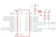
Here's the signals that are connected to the inputs and outputs:

/DS - data strobe connected to CPU
CPUCLK/20M - 20MHz clock signal that drives PDS and I/O devices
MC_26-UK7_3 - unknown signal that's output by the memory controller to flag something
A31-A28 - address signals connected directly to the CPU bus (aka fast bus)
CTRL+ADDR_DIR - controls the direction of the buffers for control and address signals that sit between the "fast" and "slow" busses
FC1 - function code bit 1 connected to the CPU
/DBFR_EN - output enable signal of the buffers for data between fast and slow busses
X-/AS - address strobe originating from a bus master on the slow bus (input or output on the PAL depending on the current bus master)
/AS - address strobe originating from bus master on the fast bus, CPU or memory controller - not actually sure if the memory controller can become a bus master or not (input or output on the PAL depending on the current bus master)
X-/DS - data strobe connected to devices on the slow bus
Y-/AS - address strobe output to bus arbiter PAL and address decoder PAL
FC0 - function code bit 0 connected to the CPU
40/20 - tells the memory controller wether to run the CPU at 40MHz or 20MHz
And here's the equations with some comments...
Code:
;CPU clock switch - low: 20MHz, high 40MHz
/o19 = /i11                    ;J106 set
     + /i8                    ;ctrl direction: slow-bus to CPU bus
     + /f18 * /f14 * i4                ;!FC0 * !AS * A31 ->0x8000 0000 or higher program space
     + /i9 * /f14 * i4                ;!FC1 * !AS * A31 ->0x8000 0000 or higher data space
     + /i4 * i5 * i6 * /f14            ;!A31 * A30 * A29 * !AS ->0x6000 0000 (slow PDS) or 0x7000 0000 (fast PDS)
     + /i4 * i5 * i7 * /f14            ;!A31 * A30 * A28 * !AS ->0x4000 0000 or 0x5000 0000 ROM or I/O


o19.oe = vcc

;dbuffer.oe
/o12 = /i8                    ;ctrl direction: slow-bus to CPU bus
     + /f18 * /f14 * i4                ;!FC0 * !AS * A31 ->0x8000 0000 or higher program space
     + /i9 * /f14 * i4                ;!FC1 * !AS * A31 ->0x8000 0000 or higher data space
     + /i4 * i5 * i6 * /f14            ;!A31 * A30 * A29 * !AS ->0x6000 0000 (slow PDS) or 0x7000 0000 (fast PDS)
     + /i4 * i5 * i7 * /f14            ;!A31 * A30 * A28 * !AS ->0x4000 0000 or 0x5000 0000 ROM or I/O
     + /i4 * /i5 * /i6 * /i7 * i9 * /f14 * f18    ;FC0 * FC1 * /AS * !A31 * !A30 * !A29 * !A28 -> CPU space -> FPU?

o12.oe = vcc

;slow /AS
/f13 = /f14 * /i2 * i3                ;!AS * !C20M * MC_flag
     + /f14 * /i4 * i5 * i6 * i7        ;!AS * !A31 * A30 * A29 * A28 - 0x70000000 fast PDS
     + /f14 * /i4 * /i5 * /i6 * /i7 * f18 * i9    ;!AS * !A31 * !A30 * !A29 * !A28 * FC0 * FC1 - CPU space for FPU
     + /f13 * /f14                ;latch
f13.oe = i8                    ;OE: ;ctrl direction: CPU bus to slow-bus

;fast /AS
/f14 = /f13 * /i2 * f15 * i3            ;!X-AS * !C20M * syncAS * MC_flag
     + /f13 * /f14                ;latch
f14.oe = /i8                    ;OE: ;ctrl direction: slow-bus to CPU bus

;nc, just for internal purposes - syncAS
/f15 = f13
     + /f15 * /i2
f15.oe = vcc

;slow /DS
/f16 = /i1 * /i2 * i3                ;!DS * !C20M * MC_flag
     + /i1 * /i4 * i5 * i6 * i7 * /f14        ;!DS * !A31 * A30 * A29 * A28 * !AS - 0x70000000 fast PDS
     + /i1 * /i4 * /i5 * /i6 * /i7 * i9 * f18 * /f14    ;!AS * !A31 * !A30 * !A29 * !A28 * FC0 * FC1 - CPU space for FPU
     + /f16 * /i1                ;latch
f16.oe = i8

;/AS to decoder and arbiter PALs
/f17 = /f14
f17.oe = vcc
I don't know which method the Tokamac uses to become a bus master as there's several different methods.
Knowing how the card actually tries to become bus master might give us a hint what's borked in Apples implementation.

