-
Updated 2023-07-12: Hello, Guest! Welcome back, and be sure to check out this follow-up post about our outage a week or so ago.
You are using an out of date browser. It may not display this or other websites correctly.
You should upgrade or use an alternative browser.
You should upgrade or use an alternative browser.
Am I screwed?
- Thread starter Brooklyn
- Start date
techknight
Well-known member
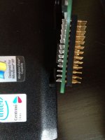
No, your fine. you can order machine based dip-sockets and steal a peg from one of those, and solder it into place. itll be slightly elevated then, but it would be repaired.
Dennis Nedry
Well-known member
I think that if you're really careful and set up a bit of a jig, you could solder your broken pin piece back on.
One idea would be to poke your pin piece slightly through a piece of masking tape, then stick the tape to the ends of the other pins, so that the broken pin is lined up where it is supposed to go, on its own. Then solder the pin to repair it and scrape away excess solder carefully with a sharp razor blade.
There is a risk with this method that the pin can break off more easily potentially leaving it stuck in a socket, so this might not be the best solution if you wish to remove / reconnect this thing a lot of times.
Dennis Nedry
Well-known member
Another option if you aren't experienced with soldering would be to get another socket that has the same pin arrangement, seat your Sonnet card into this new socket, and simply glob some solder onto that broken pin to connect it through to the new socket. This would be very easy to do and it would hold up quite well.
Trash80toHP_Mini
NIGHT STALKER
You don't even need a whole socket, a few Machine Pins on a short a strip will hold one of the pins in place, make your soldering easier and maintain the standard clearance.
PM me, I've got plenty of them and an extra postage stamp! [ ] ]'>
] ]'>
PM me, I've got plenty of them and an extra postage stamp! [
Whatever you do, you definitely need that pin. According to the diagram I'm looking at, pin A1 is BR, which I'm pretty sure is Bus Request. Without that, it won't be able to participate in bus arbitration.
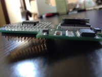
Is the pin header through-hole? That is, does it have pins that extend through the PCB? Or is it surface mount. If it is through hole, I bet you could remove the old pin and desolder it. It would be nerve wracking though to make sure you don't damage nearby pins and don't damage the through-hole copper in the circuit board. And you probably would have to do something like cut the plastic matrix around that one pin. Although, if the pins are wider closer the board, as you suggested, you may be able to carefully pry the entire plastic matrix off of all the pins, replace the problem pin and then replace the plastic matrix.
Alternatively, identify any nearby connection points for that signal on the SE/30 logic board. Solder a small wire to one of those connection points (e.g. wire wrap), and then install the upgrade and attach the other end of the wire to the pin (A1) where it pokes through the top of upgrade circuit board. You might even be able to solder a longer pin on there, and put a terminal on the end of the wire, so it can just slide over the pin, making it removable.
But if you have the clearance, DN's suggestion is probably the easiest and most reliable.
Trash80toHP_Mini
NIGHT STALKER
Nope, I meant that you'd trim the female end off the machine pin replacement for the original pin, so that it would perfectly match the height of the other pins when they act as registration points.. . . but if I don't replace them all won't the new pins stick out farther than the originals?
1) cut the end pin off the short row I mail to you.
2) remove the metal pin from the plastic frame
3) trim off the female bell end of the replacement pin
4) insert modified pin into the middle of the female side of the remainder of the strip
5) plug the strip/pin assy. onto the intact pins on the appropriate row so the replacement pin fits into the hole
6) solder it into place
7) remove the "registration strip."
With any luck at all, the cylindrical portion of the machine pin will fit into the cavity for the missing pin.
If not, you'll have to chuck the pin portion of the replacement into a drill and use a jeweler's file to "Machine" it to the correct diameter . . .
. . . maybe a tad narrower than the original to leave clearance for your "solder glob."
. . . I'll send a bit longer strip than I'd intended. [
Dennis Nedry
Well-known member
I could not wrap my head around what you were saying until you spelled it out like that. That is very clever, definitely the best method to fix it and really not hard to do at all. I'm sure I will do exactly what you described at some point in the future.
Trash80toHP_Mini
NIGHT STALKER
THX, I just reread your posts and I'd missed the part about Brooklyn having the original pin on hand, that makes things far easier. DUH-OH!!!!!!! :I
Skip all the steps referring to the modification of a machine pin if you've got the original part and substitute that. The whole megillah outlines the method for fixing a connector with a missing pin that's actually MIA. I posted the fix when I first thought of it, without really thinking about the particular situation, but it worked out OK as a more general procedure anyway.
Maybe file a tiny flat onto the original pin to align with the vertical metal strip in the pic?
I was planning on modding a couple of pins as described before I sent the strip, you've saved me some tinkering.
Thanks for that wetware reboot, Dennis, apparently I needed it! :lol:
p.s. The pin mod describes my down & dirty way of cutting bolts down to size in the field, thread a nut or two onto the bolt for deburring the threading before chucking it into the drill. At home or in the shop, a drill press makes a far superior metal/plastic/wood lathe. It's even fairly easy form a cylindrical starter section with conical thread starter into a bolt for hard to start applications.
CelGen
Well-known member
So long as you aren't going to continue moving the upgrade between computers you can resolder the pin back on and slapit in the socket and it should last. Just don't try to straighten it after soldering or it willjust break off again.
I have had to do this to to a Sonnet upgrade for a blue and white G3 and a coppermine PIII.
I have had to do this to to a Sonnet upgrade for a blue and white G3 and a coppermine PIII.
directive0
Well-known member
Trash80toHP_Mini
NIGHT STALKER
Those are for DIP ICs, IIRC. PGA pullers are more like gear pullers than tweezers.
tt
Well-known member
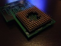
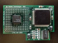
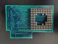
Brooklyn, would you be able to attach a photo of the other side of the board? I'm wondering if you can desolder the pin on the board side and then twist it out, root canal style and then push in a new pin from a donor socket of the same kind. The pin might just be press-fit into the plastic frame. I would practice pulling the pin out on the donor part... also there is not much room to work within. It would also be cool to see more pics in general since this part seems somewhat rare.
Mk.558
Well-known member
That almost looks like you can put the pin out of a male header and swap it out. (Something like this.) You'll want to make sure the header is long enough -- I don't know what the standard length for a male header is, but I would think a 90 degree header pin could be straightened, giving you enough length to work with.
If you pull it out "root canal style", make sure you use a ohmeter to find out where it goes to, so on reassembly you can check to see if your work is G2G. I like how compact that accelerator is.
If you pull it out "root canal style", make sure you use a ohmeter to find out where it goes to, so on reassembly you can check to see if your work is G2G. I like how compact that accelerator is.
Similar threads
- Replies
- 3
- Views
- 438
- Replies
- 14
- Views
- 1K

