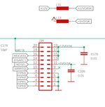
Okay, the (apparently bomarc?) schematic that someone pointed me to says that pin 11 on the floppy connectors runs to the positive side of C196/C205 (one or the other), clearly decoupling, and also runs through L12 (an inductor, damps noise on the power rail) to the 5v supply.
So, check continuity from pin 11 to the capacitor and to the inductor. Check resistance across the capacitor (should be high, preferably reading as open circuit) and the inductor (should be low). Check continuity from the inductor to the 5v intake at the PSU. Check continuity from the capacitor to the ground pins on the floppy connectors. Look for signs of leaked electrolyte or other potential corrosives. Look for sign of damaged PCB traces in the area.
So, check continuity from pin 11 to the capacitor and to the inductor. Check resistance across the capacitor (should be high, preferably reading as open circuit) and the inductor (should be low). Check continuity from the inductor to the 5v intake at the PSU. Check continuity from the capacitor to the ground pins on the floppy connectors. Look for signs of leaked electrolyte or other potential corrosives. Look for sign of damaged PCB traces in the area.