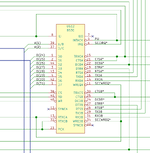
Sorry for this noobie question but what does this mean? It can't be ground, those pins are obviously marked and it can't be to nothing, those pins are left off the schematic so I'm lost on pins going to -x.
-
 Hello Guest! We're hosting a challenge to welcome vintage Intel macs to the MLA during the month of July! See this thread for more information.
 -
We've made some quality of life improvements to the Trading Post. More info here.
What exactly does "-x" mean on the SE/30 Schematic redraw ?
- Thread starter smrieck511
- Start date