-
 Hello Guest! We're hosting a challenge to welcome vintage Intel macs to the MLA during the month of July! See this thread for more information.
 -
We've made some quality of life improvements to the Trading Post. More info here.
You are using an out of date browser. It may not display this or other websites correctly.
You should upgrade or use an alternative browser.
You should upgrade or use an alternative browser.
Struggling with Performa 6360--need help
- Thread starter mloret
- Start date


Sorry, you need to spell out what your concern is. It isn't clear to meThe molex is long enough as is and I don't think the 50-pin connector is angled. In terms of the Molex and IDE connectors, do I need to remove the wiring harness?
") I'm being slow.
I'm being slow.No, I'm probably being stupid. He IDE drive in the 6360 is connected with a 50 (I think) pin cable and a powered with a Molex. These cables have very little slack and are barely long enough to make it to the IDE drive. When I replace that drive with the IDE to SD, the cables will not be long enough to reach the 50 pin connector and Molex connector on the little board at the same time. My question was whether I needed to remove the wiring harness and try to extend those cables?
Remember that they have enough slack to take the drive out - the slack you're thinking of is with the 3.5" disk almost fully removed. They're fine surely?No, I'm probably being stupid. He IDE drive in the 6360 is connected with a 50 (I think) pin cable and a powered with a Molex. These cables have very little slack and are barely long enough to make it to the IDE drive. When I replace that drive with the IDE to SD, the cables will not be long enough to reach the 50 pin connector and Molex connector on the little board at the same time. My question was whether I needed to remove the wiring harness and try to extend those cables?
40 pin50 (I think) pin cable
For the molex?They make short 4-pin power cable extensions. Easier than messing with the wiring harness IMO.
But enough surely, if you can plug in a had disk. There is more room for fingers even if the power is slightly further onto the board.I can provide pictures when I get home. The floppy drive ribbon has a lot of slack. Not the Molex to IDE Drive and 40 pin ribbon.
Otherwise a short molex extension and you'll have loads of spare.
I'd be surprised if it is an issue? Worst case I'd fit it upside down? Got any kids with small hands?Ok. I'm more worried about the 40pin.
When you're working on these, where do you mount your IDE to SD? I think that's where the confusion is coming. I was imagining it being on top of the IDE drive with the front bezel still on the case. This is probably not going to work. How do you do it?I'd be surprised if it is an issue? Worst case I'd fit it upside down? Got any kids with small hands?
For reference.
There's a plastic bracket that holds the hard drive in. Remove the hard drive, wire tie the IDE adapter to the bracket, and stick it back in. That's what I did in the 640 CD.
")
Yup, this. This is how I had a similar setup in my 6500.There's a plastic bracket that holds the hard drive in. Remove the hard drive, wire tie the IDE adapter to the bracket, and stick it back in. That's what I did in the 640 CD.
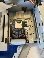
Well I’m a bit of an idiot. The IDE to SD worked great and I followed your instructions carefully. The only thing not noted was an error I got in Etcher but things still worked.
Attached you’ll see the less than ideal set up I was referring to. Is there something I should do to improve on this? The screw holes didn’t match the bracket and were too small.
Attached you’ll see the less than ideal set up I was referring to. Is there something I should do to improve on this? The screw holes didn’t match the bracket and were too small.
Attachments
Buy a rectangle of ABS plastic about 3mm thick and big enough to cover the holes in the sled. Use the sled to mark 4 holes where there are holes on the sled. Drill the 4 holes out, drill them slightly oversize to help with alignment, probably 4mm.Attached you’ll see the less than ideal set up I was referring to. Is there something I should do to improve on this? The screw holes didn’t match the bracket and were too small.
Mark the 4 holes from the SD card board in a sensible location. Drill them slightly undersize - if an M3 machine screw fits through the sled hole, Drill the ABS holes at about 2.5mm.
Buy some brass M3 standoffs. Using the standoffs as bodge thread cutting tools (perhaps hold them in a small socket or screw driver with a hex end, or in a very slow drill), tap the 4 holes for the SD Card adapter. When tapping, advance half a turn, back off 1/8th, advance half a turn... etc. Apply constant downward pressure to ensure the thread you're creating doesn't strip. Once in, confirm the thread of the standoffs doesn't protrude. If it does, use M3 washers or cut pipe with a 3.5mm interior diameter to create spacers. Screw the standoffs into your fancy new adapter plate. Screw the fancy new adapter plate to the sled, using screws with nuts on the top side. Screw the SD card adapter I to the brass standoffs.
Or use cable ties or velcro.
Last edited:
My CF-IDE only has two screw holes, so I just put a couple zip ties around the bracket arms like this. "Less than ideal", I concede, but the ties hold one end on and the IDE cable holds the other. If flops around a little when I move it but, the broken plastic in that machine flops around more


In prep for testing your board I pulled my 6360 out of storage this afternoon. I'm not sure if this is good or bad news but my BlueSCSI (v1 external) seems to work just fine with it...
Since I got it, I've used that BlueSCSI with a bunch of my Macs, kinda as a boot strap USB install drive, for setting up whatever internal drive I want to use in the Mac. The only Mac I could not get it work with was my Power Macintosh 4400.
Ugh. So I was testing a new L2 slot Cache G3 upgrade in my "Performa 6360" (thanks @pizzigri !) and realized I upgraded it with a logic board from a 6500/225 a while back. ...so my previous test report here is somewhat suspect. I know have the original 6360 logic board somewhere in storage but likely deeper than I can find at the moment since I'm in the middle of moving.
Just for the record... :-/
Similar threads
- Replies
- 2
- Views
- 293
- Replies
- 3
- Views
- 452
- Replies
- 5
- Views
- 237