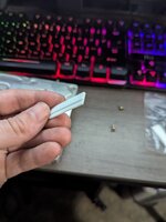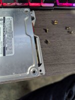


These are photos of my drive. It seems very similar to someone else's who'd made their own via cut up PCB that you based your part off of:
That was my own cut up PCB, which I actually have in my drive right now. I then made the 3D model with its exact measurements, for others to try.
Perhaps one addition you can make to your file is to add extenders to make it thicker in case the tolerances are off instead of making it a single unchange-able part?
I measured everything very precisely with calipers, and was happy with the resting position of the actuator arm, so I think it would be better to leave it as is. If when you come to install the part, you find it needs altering, I can update the model.
Now, I dug up some photos of my Maverick hard drive and it is actually quite similar to yours. Here's a comparison, along with an ELS:
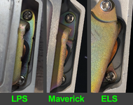
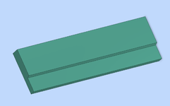
The magnet bracket inside your drive doesn't have a raised bit like the Maverick does. I've attached an STL without the notch for you to try. You can always remove material if you find it does need clearance.
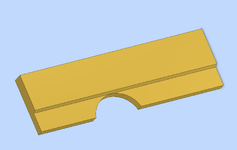
I've also corrected the design for the Maverick drive, which had the notch incorrectly offset according to my original PCB mock-up. Here's V2 (also attached):
Attachments
Last edited: