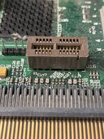
They set part of the machine ID. The boards are identical, but in part, these tell it what computer it is.
I wanted to see how they were different between the three machines, or if they were the same.
If all three were different, it would be easy to trick a 6500 or 5500 into making the TAM unique startup sound.
Discussion elsewhere means it is likely that the difference uses another method, plus nobody has provided info on the 5500 or TAM

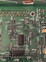
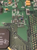
Those resistors are wired derectly to the OHare ASIC, see U5 (343S0172).
They form the so-called BoxID that can be obtained by reading OHare's CPU_ID register.
Disassembling of the logic board is not required.
The OHare CPU_ID register is located at 0xYY000034 where "YY" represents the base address of the chip assigned during machine startup.
Apple's HWInit sets OHare's base address to 0xF3000000.
Thus reading one byte at 0xF3000034 will return the BoxID set up by the above mentioned resistors.
Please keep in mind that Apple engineers used different names for well-known things causing confusions:
CPU_ID has nothing to do with the processor itself,
CPU stands for
logic board design in this case
BoxID usually means
enclosure, for example, Gazelle or TAM
Here the disassembly of the startup bong playback routine from the Gazelle ROM:
Code:
fn_FFF03D68:
    lisori    r3, 0xF3000000    # load OHare's base address
    lisori    r4, 0x34          # offset to the IDs register
    lwbrx     r4, r4, r3        # read OHare's IDs register with endian swap
    rlwinm.   r4, r4, 0,17,17   # isolate bit 6 of the Media Bay ID subregister
    bne       l_FFF03D90        # branch if it's set
    lisori    r3, 0xFFE00010    # load base address of the Gazelle bong
    b         loc_303D98

l_FFF03D90:
    lisori    r3, 0xFFE80010    # load base address of the TAM bong

l_FFF03D98:
    lwz       r4, 0(r3)
In other words, the startup bong playback routine looks at bit 6 of the Media Bay ID register.
This bit reflects the status of the DEV_ID2 pin that is connected to SRS_PRSNT signal.
SRS_PRSNT (active low) means surround sound is present if this signal is pulled low (see R207 pulldown in the Gazelle schematic).
If SRS_PRSNT is pulled low, the ROM will play the Gazelle startup bong.
Otherwise, you'll hear the TAM bong.


")

")