New-to-me 145B: what's best?

liamur

6502
Hello everyone!

I was semi-active on this forum a while ago, when I long-term borrowed a 4MB Mac Plus from one of my teachers' classrooms and had my fun with it (freshening it up, building a keyboard emulator, and attempting and ultimately failing to get Bad Apple!! working on it, because I couldn't get sound to sync without dropping frames). Eventually I ran out of things to do with it, returned the computer, and moved on.

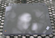
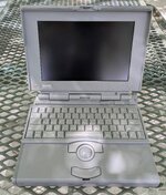
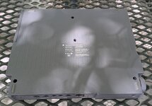
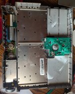
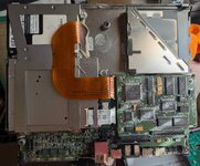
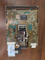
That was four-plus years ago. Yesterday I found a Powerbook 145B at an electronics warehouse for $60, including an ADB keyboard, an HDI-to-SCSI adapter, and some 1.44MB floppies (the guy there only charged me for the Powerbook; if I'd realized he'd do that, I would have taken a whole container of floppies). The computer is in great condition externally, almost scratch-free, and the insides were dusty with some spider leftovers, but cleaned up nicely (see the pictures). I don't know if it boots but I'm optimistic that it will.

I'd like to get the Powerbook up and running. I ordered one of those aftermarket power supplies, and I have access to adjustable power supplies and a cord until that arrives. Because of the Plus, I already have some 800K floppies and enough software and hardware to transfer data to the laptop, as well as a DB25 BlueSCSI v1, so I'm not worried about being able to use it. I will probably get a laptop BlueSCSI at some point. Before any of that, though, I have some questions I was hoping the community could answer:
  • I haven't looked at the display board yet, but I'm certain that those capacitors are no good anymore. Is it safe to power on the system with caps in unknown condition? I'd just like to see if the backlight turns on and if it boot bongs.
  • MacDat says that the electrolytic and polymer caps on the inverter and trackball boards probably don't need replacing. Is this true? I've worked with bad 90s caps before, they're horrible, and I'm skeptical that they shouldn't be replaced.
  • Can the floppy drive be taken apart and regreased like a Mac Plus floppy drive? It looks pretty dusty and I'd rather not lose disks or even the whole drive to an unlubricated mechanism.
  • What is the best way to (re)build a battery pack? I see a lot of different methods on here: packed-in NiMH AAs, 6V NiMH assembled packs, and even replacing 4/5A cells. As far as I can tell, the battery is supposed to be 6V, which explains the 2 sets of 5 AAs that I've seen people use. This also seems like the cheapest option, but it's not clear to me how you actually put the batteries in a circuit when they barely fit in the box.
The hinges seem to be in great shape, but it does make some concerning creaking noises when I open and close it. I'm already planning to install the 3D-printed inserts.

Thank you in advance! I hope a bombardment of questions isn't out of place.
 

Attachments

  • case_top.jpg
    case_top.jpg
    490.9 KB · Views: 14
  • open.jpg
    open.jpg
    643.7 KB · Views: 8
  • underside.jpg
    underside.jpg
    506.2 KB · Views: 9
  • inner_case.jpg
    inner_case.jpg
    922.8 KB · Views: 7
  • motherboard.jpg
    motherboard.jpg
    966.3 KB · Views: 11
MacDat says that the electrolytic and polymer caps on the inverter and trackball boards probably don't need replacing. Is this true? I've worked with bad 90s caps before, they're horrible, and I'm skeptical that they shouldn't be replaced.
The single electrolytic on the inverter needs replacement. Others are fine. I do believe there are caps in the floppy drive that I don't have noted on MacDat yet (didn't know about them until recently), and those need to go.

LCD must be recapped. Powering on will probably not damage it, but you must recap the display.

The best way to rebuild the battery is by replacing the original cells with NiCad cells of the exact same size. Finding such cells is getting difficult though, so I'd probably substitute NiMH. Going with AAs will make it easier and probably cheaper to rebuild the battery, but will get you a lower runtime. You will want to invest in a battery spot welder, this is the only proper way of rebuilding a laptop battery.

Floppy drive can be disassembled for cleaning, relubrication, and recapping.
 
Thank you! I disassembled the laptop more deeply and it appears as though the caps haven't leaked yet, or maybe they haven't let out much fluid. Either way, I'm optimistic that the recap will be pretty easy.

I don't know if this is helpful, but my floppy drive has no non-ceramic caps on it.
 

Attachments

  • floppy_drive.jpg
    floppy_drive.jpg
    1.2 MB · Views: 12
Have you checked the other side of that PCB? I think there are one or two. If not then it must have been a different revision.
 
The computer works, it even boots from the hard drive, but the floppy drive doesn't want to read. I got my capacitors and did a full recap, and when I turned on the computer, it chimed before C9 on the display (the 100uF 6V, which I replaced with a 100uF 6.3V tantalum) let out magic smoke. I replaced it and the new capacitor blew up again. Is this a known issue? The capacitor I replaced is labeled "100 6V" and I definitely put it in the right orientation both times.

Without the capacitor, the computer chimes and the backlight comes on, but there's no screen image regardless of the position of the contrast knob. I don't know if that's because the screen is fried or if that 100uF is simply part of generating an image.

Edit: I found another char mark on the corner of the bottom PCB of the display, which weirdly has no traces. I also found a loose strand of solder wick bridging a pad between the DC-DC converter blob thing and a nearby ceramic cap, which I had specifically tried to clean up but must have forgotten. I think that probably caused the previous capacitors to explode. I also tried putting an 82uF electrolytic in place and the screen still doesn't work, so I suspect I fried the whole screen.
 
Last edited:
After blowing two 6.3V caps in a row, then testing with the 82uF to no success, I was quite mad. I ended up using too much force trying to unstick the ribbon cable from the back of the screen and ripped the cable at the hinge. I put together the remnants of the machine and got on eBay in the hopes of finding a cheap donor parts machine, and I settled on a $30 PowerBook 160 listed as falling apart, with a slightly suspicious-looking screen and no trackball module, but otherwise in good condition.

USPS decided that this 160 needed to take a couple of trips around the country before getting to my mailbox, perhaps to view some scenery, so it was in transit for over two weeks. Maybe a week into its journey, I had a vague realization about capacitors at some point during that time and went to check my work, which I'd left intact. Here's the PCB of my display after my attempt at recapping:

bad_pcb.jpg

Can you spot my 11 mistakes? I installed every tantalum backwards. I assumed that the mark on a SMD tantalum indicated the same side as the mark on a SMD or through-hole electrolytic, and aligned the dash with the negative side on the PCB. This is wrong: on an SMD tantalum capacitor, the line marks the positive terminal. I might have gotten lucky, apparently tantalums really like fully igniting when they receive reverse current. Mine only vaporized and deposited their contents onto the display's RF shield.

The capacitor that exploded was the 100uF 6.3V one near the DC-DC converter. After realizing my mistake, I noticed that the 6.3V cap was the one that blew up. I suspect that this capacitor is a filter or decoupling capacitor on the 5V supply to the display, probably connected between 5V and GND or something similar, which is why it smoked while the others didn't. As a result (I hoped), maybe the display electronics hadn't been affected by the excess current and were actually fine. Around this time, I also realized that I'd probably have more fun with the 160 than the 145B, considering all the specs are the same aside from the video card, so I changed my goal from "fix the 145B with the 160" to "restore the 160 with the 145B".

A week or so later, the 160 came in and booted to the insert disk screen without a chime, and something was wrong with the two halves of the screen:

half_screen_no_backlight.jpg

but it booted and the display showed an image, which I took as a good sign. I then removed and threw out all the original tantalums from the first screen (just in case), installed new ones, put it in the 160, and...

old_screen_in_160.jpg

The old display actually works! It's in great shape without any vinegar syndrome, so I was pretty happy about this. It does apparently also mean that you can install all the replacement capacitors backward without doing harm to the display (not that I'd recommend doing so...). The new display shows a tiny amount of vinegar syndrome---enough to give off a vinegar smell on disassembly, at least initially, but not enough to cause damage to the screen outside a tiny area away from the pixel region.

There's no backlight in the picture above, and combined with keyboard issues and no chime, I assumed the interconnect cable was broken. The seller also shoved the two halves of the machine together with no regard for the cable and gave it a nasty fold. After recapping the inverter board, I grabbed an IDE cable to replace the interconnect cable. The 160 is now fully functional, except for the floppy drive, which needs oiling and more testing.

The tiny piece of solder wick that I initially blamed appears to not have done any damage. I'm not sure it was even making a connection at all, it may only have been floating in the general area of the DC-DC converter and C12 on the display PCB.

I quite like how the grayscale looks, even with the passive matrix row-column bleed. You can see in the picture below that there's still a bit of that half-screen effect (a couple pixel rows beneath "Mac(tm) OS") that the display showed before I replaced the interconnect cable. It causes alternating columns of pixels on the bottom half of the screen to be dimmer. This isn't really a usability problem, especially since it goes away at lower grayscale depths, but it is a little annoying. I wonder if it's a data integrity issue or something.

grayscale_boot.jpg

The moral of this story, if you will, is that you should do your research on the components that have a coin toss's chance of blowing up in your face before you install them.
 
The tantalum’s positive stripe notation is dumb and has tripped many hobbyists up, so don’t beat yourself up too much. It’s a painful lesson but at least you know now.
 
Back
Top