Did you use the bitswapped images on Bolle’s GitHub? The Reloaded board needs byte-reversed code and this could potentially trip some people up.
Thanks for your replies! Very much appreciated!
Yes I directly burned the ROM images from the Github repo without any modification.
Then read them back to verify checking the check sum hashes which matched.
I did this for my first two boards and it’s a great idea for testing chips, although I’ve damaged a few cosmetically during removal even with a chip puller, so take care with that.
The chips need to be very clean before they’re inserted, so that’s one thing to check - one of them might not be making perfect contact.
Each chip was carefully removed and then painstakingly cleaned.
First I removed residue and buildup by very gently scraping pins which were effected. Then fluxed some braid and cleaned each until no access solder was apparent and they were very reasonably silver in color and uniformly smooth.
I then rinsed with ISO and brushed thoroughly with a toothbrush to clean.
Very carefully I pried each pin out a fraction from the underneath of the IC by very carefully inserting and levering a suitable tweezer tip in the gap between where the leg ends and the cavity that constrains their position. This ever so slightly shifted the pins outward and approximately back to their original position after being slightly compressed by the process of removal and cleaning.
Another thing is, it would be good to know if you’re getting any sad chimes, as would tell you if the ROM is being accessed, but without the speaker jack soldered in, audio won’t get routed to the internal speaker header. So either add that in, or solder bridge the two pads on the underside of where that connector goes (and make sure an internal speaker is connected).
View attachment 92472
Thanks for the advice and good catch. But this is a slightly older photo of my board and have since soldered this and tested with a speaker and I get no bong what-so-ever. Which means that the boot is not even getting to ROM or not even far enough into testing.
I've checked the RESET line and it goes HIGH shortly after starting and stays there.
I've check the oscillators and am getting ~32Mhz on the main and ~16Mhz on the CPU and ~32khz on the RTC.
I've checked voltages and they are very good just over 5V and pretty much right on 12V. And -12V is also present and strong.
As for the VRAM, if you look closely it's almost correct. I would have thought uninitialised RAM would have been far more random than this pattern - it's like it trying to draw the checker pattern but something isn't fetching from the correct spot, like bit-0 looks "out"
Anyway I had ordered some new Video RAM which should be arriving soonish.
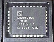
Also here are the EPROMs I am using - compatible?


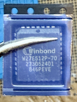


")