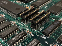
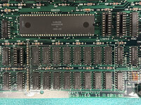
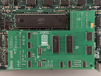
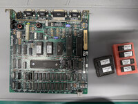
I have the original ROM from my other 512k board that now has a ROM-inator. Probably similar to the other board.Mmm... so, those ROMs you have installed—342-0220-B and 342-0221-B—are 64KB ROMs. We haven't tested the RAM Card with the Mac 128K/512K ROMs yet.
it has similar
Hi - 342-0220-A
Lo - 342-0221-A
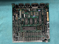
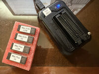
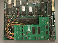
I also am putting together a BOMW ROM-inator board that I had made recently from JLCPCB and have several of the recommended ROM's for that board
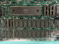
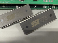
SST39SF040-70-4C-PHE
I can program with the standard ROM or just update to the new file to work with the expansion card.
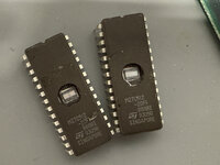
I also have some ST M27C512, but I have had those for a while...
What ever you think would work best.
")