-
 Hello Guest! We're hosting a challenge to welcome vintage Intel macs to the MLA during the month of July! See this thread for more information.
 -
We've made some quality of life improvements to the Trading Post. More info here.
You are using an out of date browser. It may not display this or other websites correctly.
You should upgrade or use an alternative browser.
You should upgrade or use an alternative browser.
Early Macintosh home brew 4MB memory upgrade board development
- Thread starter Golden Potato
- Start date

Are there any photos of version 3 completed? I am looking to compare parts. The Github page has a dead link for photos.
I ordered from the Mouser cart (thank you Joopmac) except that J11 and J12 headers are backordered and not in stock. I am guessing this header may work found on Amazon...
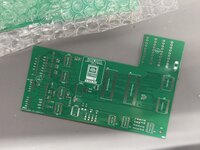
The PCB's I ordered were completed and shipped.
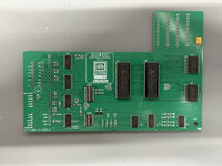
Oops! I forgot to add those connectors to the BOM. Here's a picture of the back. They are 2 mm pitch through-hole JST connectors, like these on Amazon (the link you provided doesn't seem to be working).
I actually bought the ones I used from Ali Express
These pictures are from the initial PCB run used for testing. The KiCad files on GitHub represent a slightly newer version with a couple of minor fixes and some improvements. The dip switches were the areas that were changed.


Last edited:


Very cool. Thanks for the info. I purchased the correct headers for J11 and J12. I must have bought the last ones. Same Amazon vendor had listing on eBay as well. Both are out of stock.Oops! I forgot to add those connectors to the BOM. Here's a picture of the back. They are 2 mm pitch through-hole JST connectors, like these on Amazon (the link you provided doesn't seem to be working).
I actually bought the ones I used from Ali Express
These pictures are from the initial PCB run used for testing. The KiCad files on GitHub represent a slightly newer version with a couple of minor fixes and some improvements. The dip switches were the areas that were changed.
View attachment 85665
View attachment 85663

Pack of 5 B6B-PH-SM4-TB Connector Header Surface Mount 6 position 0.079" (2.00mm | eBay
B6B-PH-SM4-TB Connector Header Surface Mount 6 position 0.079" (2.00mm). PICK UP OPTION. JM38510/01401BJA Single General Purpose 24 Pin Dip. Buy now and save!
www.ebay.com
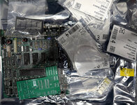
I ordered enough components from Mouser to make two. The RAM chips (AS4C1M16E5) are coming from China and won't be here until May.
I am hoping while I wait for a diagram to connect the jumper wires from PCB to the board. Currently I have BOMW ROM-inator installed on my 512k. So some direction with connecting it to the board would be greatly appreciated.
Thanks again. This is a great project.
Oops! It looks like C1, a 10uF tantalum capacitor (case code 2312/6032), was mistakenly excluded from the bill of materials in its footprint attributes. So sorry about that!Is it correct i have a empty space at C1?
Thanks=)
i am going to use:
10uf tantalum polymer
I do not use yellow tantalum anymore since i saw a capacitor burn like a match on a SE/30 board
Addendum for the mouser cart:
correct JST headers
*The header in my first cart was wrong; SMD and not through hole (the wrong ones are not in stock so probably one does not have these yet)
correct JST connectors
the pins
Mouser is ordered, JLC is on their way and the RAM ic's are here already
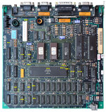
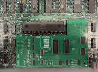
All my parts are in. I am preparing to build two expansion cards. I did create a photo parts location with pin locations. (please correct me if this is wrong).
I have all the proper headers, but am wondering about stacking and proper header height so the board can clear the case. Are headers soldered onto the IC and then card is placed on top? Or can the IC's be removed and placed on the expansion card?
I haven't seen any images from the top of the expansion board (Version 3) mated to the motherboard.
This is a great project.
Attachments
The GitHub repository's readme explains that you have two options: either solder sockets onto the ICs (piggyback) and male-to-male pin headers onto the expansion card, or do the reverse by soldering the sockets onto the back side of the expansion card and the male-to-male headers onto the ICs. I choose solder the sockets on top of the ICs (piggyback).I have all the proper headers, but am wondering about stacking and proper header height so the board can clear the case. Are headers soldered onto the IC and then card is placed on top? Or can the IC's be removed and placed on the expansion card?
Oh, one more thing! For the connections at RP2 and RP3, remember to solder socket pin headers to the back of the expansion card. Then, add just one row of male-to-male pin headers to these. On the LB side, solder socket pin headers at RP2 and RP3. This way, all connections will be equally leveled.
Last edited:
Unfortunately, I haven't had the chance to take pictures with the expansion card installed yet. Right now, I have a mess of wires connected to my LB trying to make another project work. But don't worry, I'll assist you anytime you need.I haven't seen any images from the top of the expansion board (Version 3) mated to the motherboard.
Thanks for the photo! Just glancing at it, I think some of the pin locations might be incorrect. Let me create an image with the right pinouts for us to double-check.All my parts are in. I am preparing to build two expansion cards. I did create a photo parts location with pin locations. (please correct me if this is wrong).
Alright, Readme.md is updated! You'll now find a picture right after the description of the signals that connect to the JST connectors on a Macintosh 512K LB (630-0118). This should definitely make things a bit easier.
I tapped the /RAS signal from the TSM chip (pin n°14), as shown in the recently added picture. However, the table in the readme.md indicates tapping it from the left leg of R4. Don't worry, both locations are the same signal. Use whichever you prefer.
.jpg")
I tapped the /RAS signal from the TSM chip (pin n°14), as shown in the recently added picture. However, the table in the readme.md indicates tapping it from the left leg of R4. Don't worry, both locations are the same signal. Use whichever you prefer.
Last edited:
While physically possible, I haven't explored desoldering and transferring the ICs. Our design offers a much simpler and reversible solution: remove the card, and your LB is back to its original configuration thanks to the socketed RP2 and RP3.Or can the IC's be removed and placed on the expansion card?
This is really helpful information. Thank you.Alright, Readme.md is updated! You'll now find a picture right after the description of the signals that connect to the JST connectors on a Macintosh 512K LB (630-0118). This should definitely make things a bit easier.
I tapped the /RAS signal from the TSM chip (pin n°14), as shown in the recently added picture. However, the table in the readme.md indicates tapping it from the left leg of R4. Don't worry, both locations are the same signal. Use whichever you prefer.
View attachment 85999
I will be starting to build my board this week.
I was just looking at the BOMW ROM-inator install instructions and it uses the same two pins as the RAM expansion card (pins 45 and 46. So this would mean two wires connected with those pins. Just trying to make sure I get this correct.
Thanks again for the new information.
Thanks again for the new information.
Attachments
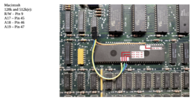
Since these address bits from the CPU aren't connected anywhere else (on Macs 128K, 512K, and 512Ke), they are sourced from the single location where they exist. If you have concerns about having two wires (one for the memory expansion and another for the ROM-INATOR) connected to A17 and A18, please don't. There is nothing wrong with this; both cards require these input signals, and that's all.I was just looking at the BOMW ROM-inator install instructions and it uses the same two pins as the RAM expansion card (pins 45 and 46. So this would mean two wires connected with those pins. Just trying to make sure I get this correct.
I strongly advise you to install the memory expansion card without the ROM-INATOR first. Reinstall your original 128KB ROMs from the Macintosh 512Ke.
Once you have confirmed that the machine boots and the new memory size is fully detected, you can then begin the installation process for the ROM-INATOR.
As I clearly stated in the readme.md file in the repository, the ROM_INATOR ROM image needs to be patched. Otherwise, the machine will freeze immediately after the "Welcome to Macintosh" window appears if the memory expansion board is installed concurrently.
I have two sets of the ROM-INATOR ICs, one set is patched and the other not. I recommend that you do the same.
I no longer have the ROM-INATOR board installed; instead, I installed the replica board of the MacSnap SCSI interface, made by Demik.
Having the SCSI interface and the ROM-INATOR integrated into a single board would be the ideal solution to have both.
Last edited:
Thankfully I have two Mac 512k boards. I was planning on installing the RAM expansion card on the one without the ROM-inator as a test.Since these address bits from the CPU aren't connected anywhere else (on Macs 128K, 512K, and 512Ke), they are sourced from the single location where they exist. If you have concerns about having two wires (one for the memory expansion and another for the ROM-INATOR) connected to A17 and A18, please don't. There is nothing wrong with this; both cards require these input signals, and that's all.
I strongly advise you to install the memory expansion card without the ROM-INATOR first. Reinstall your original 128KB ROMs from the Macintosh 512Ke.
Once you have confirmed that the machine boots and the new memory size is fully detected, you can then begin the installation process for the ROM-INATOR.
As I clearly stated in the readme.md file in the repository, the ROM_INATOR ROM image needs to be patched. Otherwise, the machine will freeze immediately after the "Welcome to Macintosh" window appears if the memory expansion board is installed concurrently.
I have two sets of the ROM-INATOR ICs, one set is patched and the other not. I recommend that you do the same.
I no longer have the ROM-INATOR board installed; instead, I installed the replica board of the MacSnap SCSI interface, made by Demik.
Having the SCSI interface and the ROM-INATOR integrated into a single board would be the ideal solution to have both.
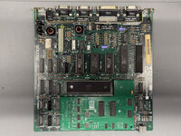
Mmm... so, those ROMs you have installed—342-0220-B and 342-0221-B—are 64KB ROMs. We haven't tested the RAM Card with the Mac 128K/512K ROMs yet.Test fit. Very nice fitment!
I just need to place headers on the board and then run jumper wires.
Similar threads
- Replies
- 22
- Views
- 2K
- Replies
- 61
- Views
- 25K
- Replies
- 0
- Views
- 2K
- Replies
- 203
- Views
- 54K