• Hello MLAers! We've re-enabled auto-approval for accounts. If you are still waiting on account approval, please check this thread for more information.

croissantking's conquests

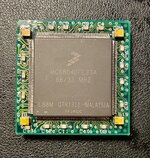
So I desoldered the LC040 chip off my QFP-PGA adapter board, and fitted a Freescale 040 onto it. I gave it a whirl on one of my Quadra 840AV boards, with a heatsink on top, and it’s unreliable as hell. It usually chimes, but freezes often, and when it did boot up, trashed my hard drive partition and caused weird behaviour.

I’ve used contact cleaner (deoxit) spray on the PGA pins to no avail. I’ve gone round the 040 chip again with flux and reflowed each pin, and will give it another test today. But I suspect the problem is with the adapter board design itself as I had the same problem with the LC040 chip that was on there previously. I’m surprised as it’s basically a straight through adapter with some decoupling capacitors.
 

Attachments

  • IMG_1779.jpeg
    IMG_1779.jpeg
    2.2 MB · Views: 59
  • IMG_1780.jpeg
    IMG_1780.jpeg
    3.2 MB · Views: 34
Last edited:
A quick pic of my desoldered QFP 68040 chips, ready for testing and reuse in future projects. Some of them have corroded pins, which will be difficult to repair. They can be used to upgrade the PowerBook 500 series, as well as 190 and Duo 280 with a full FPU. They can also be placed on an adapter board for use in a desktop machine. I suspect most if not all will be capable of 40MHz operation.

IMG_1827.jpeg
 
I picked up a small IR preheater, which I plan to use to swap out the Grackle chip on my Beige G3’s logic board, exchanging it for a 100MHz rated part.

I’ve never done BGA rework before, but I have a scrap board to practice on first.

IMG_3254.jpeg
 
I have the same one, seems to work pretty well. I've never actually done a BGA with it either, but I use it when I'm using hot air to remove a large SMT part on any board I care about and don't want to warp.
 
Last night I installed a 100MHz XPC106 chip on my Beige G3 logic board, replacing the stock 66MHz part. I booted up the Mac afterwards and it runs fine. It’s my first time doing BGA rework so I’m really pleased it’s been successful. (It’s actually not as hard as I thought!)

I used the IR preheater shown above which is quite small compared to the size of the logic board but luckily there was no warpage.

IMG_3305.jpeg

IMG_3313.jpeg

I’ve only run it at 66.8 MHz so far, but today I’ll give it a brief whirl at 83.3 MHz and then attempt to clock it to 100MHz by modding the relevant pull up/pull downs R49 and R52 as documented in the Gossamer DVT schematics.
 
Awesome! So glad you finally got the chip after all the setbacks we had.. I’m excited to see if it actually bears fruit as if it does I will wanna try it on my AIO G3s logic board (which has a G4 400mhz CPU in it)
 
Thanks! No, it’s salvaged from one of Durosity’s battery bombed boards. I reballed it myself.

I tried the resistor mod for 100MHz operation, but alas, no signs of life. I am pretty confident I set up the GracklePLL correctly (‘1000’ for 3:1 operation according to the datasheet): so R52 (PLL0) pulled up, R49 (PLL1) pulled down, and both shunts (PLL2+3) on the jumper block fitted.

I think there could be a number of reasons for the failure to boot but the ones which most come to mind are that this config is either not supported by the clock generator or by the ROM. Or it could be that I’ve just made a silly mistake somewhere.
 
Last night I installed a 100MHz XPC106 chip on my Beige G3 logic board, replacing the stock 66MHz part. I booted up the Mac afterwards and it runs fine. It’s my first time doing BGA rework so I’m really pleased it’s been successful. (It’s actually not as hard as I thought!)

I used the IR preheater shown above which is quite small compared to the size of the logic board but luckily there was no warpage.

View attachment 84924

View attachment 84925

I’ve only run it at 66.8 MHz so far, but today I’ll give it a brief whirl at 83.3 MHz and then attempt to clock it to 100MHz by modding the relevant pull up/pull downs R49 and R52 as documented in the Gossamer DVT schematics.
Awesome! glad the swap itself worked :) have you tried it at 83.3Mhz just as a sanity check? its also worth making sure all your RAM is PC100 or even PC133 rated, as I imagine PC66 RAM might not overclock to 100Mhz, and also of course make sure the CPU multiplier is set so that 83.3Mhz or 100Mhz, the CPU is not going to try and clock itself too high
 
Also what rom version is the board running? I seem to recall there were 3 for the Beige G3 and the 1st gen was buggy.
 
Awesome! glad the swap itself worked :) have you tried it at 83.3Mhz just as a sanity check? its also worth making sure all your RAM is PC100 or even PC133 rated, as I imagine PC66 RAM might not overclock to 100Mhz, and also of course make sure the CPU multiplier is set so that 83.3Mhz or 100Mhz, the CPU is not going to try and clock itself too high

Yes! It works perfectly at 83.3Mhz - I am already happy about that as it used to be a bit unstable. I have all PC133 RAM and during testing I set a 3.5x multiple for my 350MHz CPU. So all good there.

I updated the thread we have over on MacRumors (you must have figured out I’m the same person) with a bit more info. @joevt has pointed me towards a HWinit table in ROM that we need to look at modifying. It seems likely the firmware only proceeds to POST if it detects one of the bus speeds listed.

Also what rom version is the board running? I seem to recall there were 3 for the Beige G3 and the 1st gen was buggy.

This is going to sound funny, it’s a Rev D.

It’s a special, unreleased ROM that @stynx sent me to play around with. As far as I can see it’s almost identical to the Rev C with like one or two minor changes… but it does call itself a $77D.45F3 (as opposed to 45F2 for the Rev C). No idea what’s the story with it or why it exists, but it’s cool to have!
 
Last edited:
It’s a special, unreleased ROM that @stynx sent me to play around with. As far as I can see it’s almost identical to the Rev C with like one or two minor changes… but it does call itself a $77D.45F3 (as opposed to 45F2 for the Rev C). No idea what’s the story with it or why it exists, but it’s cool to have!
$77D.45F3 is discussed in a couple places.
https://68kmla.org/bb/index.php?thr...on-1st-gen-clamshell-ibooks-model-m2453.33055
https://68kmla.org/bb/index.php?threads/the-820-0961-a-mystery-g3-3-3v-flashrom.48746
https://68kmla.org/bb/index.php?threads/getting-g3-whisper-perch-usb-working.43681/post-553813
 
I tried the resistor mod for 100MHz operation, but alas, no signs of life. I am pretty confident I set up the GracklePLL correctly (‘1000’ for 3:1 operation according to the datasheet): so R52 (PLL0) pulled up, R49 (PLL1) pulled down, and both shunts (PLL2+3) on the jumper block fitted.

Pretty much the same issue I ran into with the iMac G3 CPU card I installed a 100MHz Grackle on, no matter the settings I tried, no signs of life.
Will follow this to see if it might be an OF/ROM issue!
 
Pretty much the same issue I ran into with the iMac G3 CPU card I installed a 100MHz Grackle on, no matter the settings I tried, no signs of life.
Will follow this to see if it might be an OF/ROM issue!
I was wondering how you’d been getting along with that.

The Gossamer HWInit includes the following table of bus and DEC frequencies:
Bus freqency | Decrementer frequency
50000000, | 12500000
60000000, | 15000000
66666666, | 16666666
75000000, | 18750000
70000000, | 17500000
78750000, | 19687500
66820000, | 16705000
83000000, | 20750000

@joevt does the trayloader iMac have the same HWinit table in ROM?
 
This table is from the SC608 clock generator datasheet (download link), used on both the trayloader and Beige. It seems to suggest that the bus speed is set here rather than on the Grackle itself? Or that the settings here need to tally with the Grackle PLL setting (and probably the ROM as well).

IMG_3349.jpeg

The clock generator on the B/W/Yikes is a different part (SC683) and not pin compatible.
 
Most of the Beige overclocking guides online used to say that the jumper block lets you set up the PCI speed and then the bus multiplier - a dynamic calculation - but it really seems like all we’re doing is choosing from one of six hard-coded presets in the clock generator. If this is how it works then I’m not too sure how relevant the Grackle PLL setting is at all.

It seems like both the clock generator and the ROM code are barriers to any progress here.
 
Back
Top