• Updated 2023-07-12: Hello, Guest! Welcome back, and be sure to check out this follow-up post about our outage a week or so ago.

Transformers for homemade LocalTalk/PhoneNet dongles

halkyardo

Well-known member
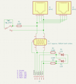
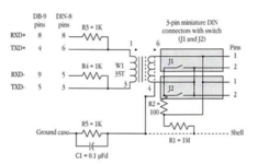
Just to get the diagrams in question into one place, here's the diagram from A-4
1711500302285.png
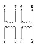
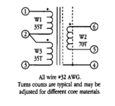
... and here's the diagram from A-6 and A-7
1711500355097.png

It looks like the 'computer' side of the transformer is center-tapped, but the A-4 diagram is slightly contradictory as to how it is wired up - if you believe the turn count on the A-4 diagram, then only one half of the computer-side winding (35 turns) is being used, effectively giving a 1:2 ratio. But if you believe the pin numbers, then the whole winding is used with the center tap left disconnected.

Regardless, the transformer in the adapter that I cracked open is definitely not center-tapped on either side, and since the inductances on both sides of it are roughly the same, then I'm pretty sure that the turn counts are probably the same.
 

Mk.558

Well-known member
The design for the single port adapters is different than the twin port adapters.


That's all I've got for a twin port adapter. I'd have to break open my single port adapter to find out what is inside it, which I have no present intentions of doing. :)

US Patent 5003579A said:
The transformer 30 is typically a Coilcraft™ P104--i.e., a 1.0:1.0 turns ratio transformer with 100-1000 turns in each of windings 32, 34 of 20-30 gauge wire about an E-form closed loop former of cross-section about equal to a winding loop cross-section, affording a high electromagnetic inertial mass and reducing conductive line interference. The interwinding capacitance of the transformer is very low, typically 7 pF, and the voltage isolation between windings is well over 350 volts, typically 3500 V-RMS, further isolating static charges on the network. The DC resistance of each of windings 32, 34 is under an Ohm, preferably 0.2 Ohms maximum. (Source)

I would just use an Ethernet isolation transformer and just use 2-4 of the pins. I was unable to find such model: all I get are power inductors, which ... are not technically the same thing, and AFAIK you want something "audio grade" so you won't have packet losses and stuff. Starting to get out of my lane...
 

halkyardo

Well-known member
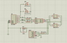
Oops, wasn't paying attention while tracing that schematic. Got the LED wiring and the order of the serial port pins wrong. Here's a second attempt that I'm pretty sure is right.

1711502691529.png
 

cheesestraws

Well-known member
The patent for PhoneNET gives a model number!

Yup, @Mk.558 noted that as well but I didn't have time to chase last night. The thing that slightly baffles me is that the datasheet for this claims to be a common mode line choke: https://www.coilcraft.com/getmedia/39589b7d-f6b7-4e06-af97-0ea2528ddb6c/p104.pdf which I mean, does look like it's a 1:1 transformer being used at 90 degrees to how it usually would be, but at the same time if that is actually what is in use in PhoneNet boxes, what we're doing here is an act of profound neurosis, because that's not even designed as a transformer for signals at all, and if that works, anything probably will :p.
 

DBJ314

Member
... is it just me, or does the Inside Appletalk chapter on the transformers not specify what frequency the capacitance and inductance are measured at?

Capacitance and inductance (attempt to) tell you what properties the component will have at every frequency.

Capacitance measures the ability of a component to store electric energy, most commonly in an internal electric field. A capacitor that allows a charge of one coulomb to accumulate on its plates when it’s subjected to one volt is said to have a capacitance of one farad (F). Another way to look at it is that a 1 F capacitor, when supplied with a constant 1 A current for one second, will be charged to 1 V.
The unit of inductance — one henry (H) — corresponds the behavior of a device that, when subjected to a current rising at a rate of 1 A per second, opposes this (rather leisurely!) change by developing 1 volt across its terminals. The effect is symmetrical, so if the current plunges, the voltage dips negative as the inductor is trying to sustain the flow.
Those quotes were taken from this blog post: https://lcamtuf.substack.com/p/primer-core-concepts-in-electronic. I found it a few days ago, and before that I had no idea there was more to farads and henrys than just blindly copying them from schematics or online calculators.
 

cheesestraws

Well-known member
Capacitance and inductance (attempt to) tell you what properties the component will have at every frequency.

This is only true for ideal components, unfortunately: once you get into actual physical components, both capacitance and inductance are frequency-dependent, because physics is a mess and I'm amazed that people understand it in detail. This is why designing things that work at radio frequency is so painful. If you have a look, for example, at this datasheet (which is just a random RF inductor I pulled from google) you'll see it has a graph of inductance over frequency which shows really quite a large change over the designed parameter space of the inductor:

Screenshot 2024-03-27 at 17.54.54.png

This is why decent LCR meters have a choice of frequencies to measure at: if you don't measure your inductor (or capacitor) at something like the frequency of the signal that's going through it, you won't get the same answer. And it's also why transformers and the like tend to specify at what frequency the measurements were made (unless they're basically single-purpose). The datasheet of the transformer that @tashtari linked to, for example, notes what measurement conditions - including frequencies - were used to reach the numbers it gives:

Screenshot 2024-03-27 at 18.04.09.png

You'll see the same if, for example, you look at this datasheet for the first ethernet transformer that I found on RS:

Screenshot 2024-03-27 at 18.09.06.png

The reason why I bring this up is not that I think in this case it matters, but because a serious specification for an inductive component should include it. This leads me to suspect that the chapter in IA is not really a specification, but more a 'here's what we built, have at it' kind of spec. Which leads me to believe, in turn, there's more wiggle room here than what the chapter appears to specify.
 

tashtari

PIC Whisperer
Here's another cheap option, it's not quite Ethernet, but it's a cousin thereof...

500 µH, even. It's 1:1:2:2 but according to the schematic in the manual, you can get just the 1:1 part of it by connecting to pins 1-2 and 7-8:
View attachment 71590
It WORKS!

I breadboarded myself a simple PhoneNet dongle, shorting 2-3 and 6-7 and connecting the differential outputs of a 65HVD08 to 5 and 8, and a phone wire to my PhoneNet network and a 120 ohm resistor to 1 and 4, and was able to send and receive some data. =D

I haven't put it through its paces or anything so I don't know if there are huge rates of data loss associated with it, but this transformer, at least, seems like it might be a winner.
 

tashtari

PIC Whisperer
Now attach 30 additional devices and see if it still works 😇
That's a fair response. =P Like I said, haven't put this through its paces, nor do I have a big enough PhoneNet network to do so...

...So what to do with this information, I wonder? I could spin a PCB and make PhoneNet dongles, I guess. MiniDIN-8 pigtails seem to be no easier to come by than actual PhoneNet dongles, but I could snip apart S-video cables and pull out the key, that'd cover the TxD and RxD pins, which is all that's really needed... I just wonder if the demand is there.
 

GRudolf94

Well-known member
In the list of things I once designed and forgot to release is a PhoneTalk box. I have P/N PH9184 listed on that.
 

tashtari

PIC Whisperer
Would a transformerless design be possible using capacitive coupling?
I believe that's what CapNet is. I'm not enough of an electrical engineer to say with authority why/how it's inferior to using a transformer, but perhaps someone else here is...

Interesting, not quite the 20 mH that Apple calls for but at 15 mH, it looks like it's the only one in the neighborhood that Digikey sells. I'm still not clear on what the inductance affects, considering that 500 µH seems to work fine...
 

GRudolf94

Well-known member
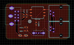
I guess I could publish this. Eh. I never came to any conclusion about whether the inductance neeeeeds to adhere that strictly to the standard because I ended up never having space to set up two Macs in an AppleTalk network.
 

Attachments

  • 1711850678355.png
    1711850678355.png
    69.5 KB · Views: 12
  • 1711850703535.png
    1711850703535.png
    98.7 KB · Views: 10

tashtari

PIC Whisperer
I guess I could publish this.
I'm always in favor of more open designs! Curious, though: is there a point to the 1 MΩ resistor and 100 nF cap if the only 'ground' in the board is the pour? Also, smol suggestion: if you replace the 6P4C with a 6P6C, even if you don't connect the extra two pins, it'll help out people like me who bought a huge bag of 6P6C jacks from a surplus retailer and have no idea how to use them up. =D

Like I said, haven't put this through its paces
I'm wondering how I might do this. I wouldn't think there would be any passive loading effect, that is, as long as the other side of the transformer is unconnected or high-Z'd, it shouldn't matter how many transformers you have on the line... right? Or does the high inductance spec exist for the purpose of reducing that loading effect, maybe? My lack of EE background strikes again.
 
Top