-
Updated 2023-07-12: Hello, Guest! Welcome back, and be sure to check out this follow-up post about our outage a week or so ago.
You are using an out of date browser. It may not display this or other websites correctly.
You should upgrade or use an alternative browser.
You should upgrade or use an alternative browser.
Short when CRT board connected
- Thread starter benanderson89
- Start date
techknight
Well-known member
2nd. Yes, the tubes are all the same. you can buy the tube and swap the yokes.
and yeap in a previous post, it discharges voltage into the gun to blow debris off. you have to tap the neck of the CRT sometimes while discharging it.
You really need to do this properly with a CRT tester. because otherwise you need something like an old charged photoflash or something. over 400V which is dangerous enough.
benanderson89
Well-known member
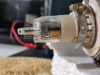
Looking at the neck of the tube, are you ABSOLUTELY SURE pins one and five are supposed to NOT have continuity? They look like one solid piece of metal from here (pins covered with blue and pink plastic commoned an outer sleeve around the cathode)
I have a funny feeling I'm chasing yet another red herring (since I was told no pins except 3/4, the filament, should have continuity) and both my tubes are absolutely fine.
Even so, I've used my little bench supply to test the heater filament and it holds nice and steady. Likewise I've blasted pins one and five with everything from 0.3A up to 5A in short bursts (whilst tapping the neck) and I think I've successfully blown some crap off of G1 as the resistance is now sitting comfortably at around 2ohm, which is about what it should be if old forum posts as far back as 1999 are any indication.
I think on Monday I'll contact a local TV Repair man who's been in the business for decades. He'll be far better than me at tracing the analogue/sweep board and finding out where the actual short to ground is.

benanderson89
Well-known member
This is the second tube I have that just got delivered from eBay, so yeah it needs a bit of a clean and pin 1 bent back into place.
Trash80toHP_Mini
NIGHT STALKER
Haven't had enough coffee yet, but wondering about that partial screen draw, failure and why you might have the same fault now with two different CRTs tested? Dunno electronics enough to be of help there, but my first blurry thought was wondering if you've got a memory failure that's screwing with the frame buffer? Dunno if you can get chimes with the the neck board unplugged in a Classic, do you get them in that config? Have you got a memory expansion card installed, if so remove it just to see what happens? The first two MB are soldered, no?Hopefully the monitor isn't shorted, and I'm 50% sure that it may not be the problem since on first power up it did actually come to life (would draw one quarter of the screen then centre the beam to a single dot very rapidly as the computer struggled to boot, the speaker clicking each time it tried to scan -- after that first attempt the computer doesn't anything except crackle the speaker and spin up the fan).
benanderson89
Well-known member
1MB is installed on the motherboard since the Classic is basically a Macintosh Plus. This is what the screen scan in question looked like. It wasn't slow enough to see it draw; it was so quick I'm sure anyone with epilepsy would go into a fit. After switching off the machine and switching it back on, nothing happens.Haven't had enough coffee yet, but wondering about that partial screen draw, failure and why you might have the same fault now with two different CRTs tested? Dunno electronics enough to be of help there, but my first blurry thought was wondering if you've got a memory failure that's screwing with the frame buffer? Dunno if you can get chimes with the the neck board unplugged in a Classic, do you get them in that config? Have you got a memory expansion card installed, if so remove it just to see what happens? The first two MB are soldered, no?

I've not ran tests on the tube inside my Classic since that's off in storage, but I've tested the tube I've had delivered. It's definitely not a heater short as the filament glows and everything holds nice and stable. No continuity or resistance between either the heater pins to anything else.
The only short is Pin 1 to Pin 5, and as it turns out, my old and cheap meter is dying and there's actually a dead short, no resistance at all. The reading I was getting from my meter was it's own internal resistance (you get the same result touching the two probes together).
So it's not G1-K, G1-H or H-K. G1-G2 short, perhaps?
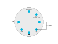
Here's the pin-out as seen from the back of the tube and labelled. It's basically the top and bottom pins that have a dead short together.

Trash80toHP_Mini
NIGHT STALKER
In that case I'd test the rheostat(?) that controls brightness for the short as my first step? Maybe you can take it out of circuit, replacing it with a resistor for testing?
Last edited by a moderator:
benanderson89
Well-known member
The rest of the computer is fine - it's only the when the tube is connected that the low voltage side shorts. The short is on the pins of the CRT itself.In that case I'd think I'd test the rheostat(?) that controls brightness as my first step?
Trash80toHP_Mini
NIGHT STALKER
The brightness control is out of circuit when the CRT is disconnected, no?
benanderson89
Well-known member
There's no shorts anywhere when the CRT is disconnected.
Trash80toHP_Mini
NIGHT STALKER
That's what has me thinking brightness control circuit, which is cut out of the equation when the neck board is unplugged, no? Don't mind me if my suggestions make no sense, still half asleep. :blink:
benanderson89
Well-known member
Theres no short to ground in the brightness circuit so we can rule that out. 
The short is the tube itself.
The short is the tube itself.
Trash80toHP_Mini
NIGHT STALKER
I'll be quiet now. [ ]
]
techknight
Well-known member
To answer your earlier question, I went off the BOMARC drawn schematic, Unless there is an error, there should NOT be anything between 1 and 5.
When I get home, I will double-check my CRTs. all of mine are good.
When I get home, I will double-check my CRTs. all of mine are good.
Last edited by a moderator:
benanderson89
Well-known member
Back from the repair shop! IT'S ALIIIIVE!
Pins 1 and 5 are supposed to be together. 1 is G1 and 5 is ground of G1. A lad from the vintage television forums said that's what it's for. My actual issue was that two caps, the only two I didn't replace that were hidden under a massive gob of hot glue, had went open circuit. So there was a floating voltage to ground and no current to drive the CRT. End result is that the power supply protection circuitry kicked in.
I still have a "shimmering" issue with the display after it's had a chance to warm up, so I think there's one more old cap that needs to be removed on that analogue board or I need to adjust the voltages just a tad.
But either way, it works. I'll be ordering an SD2SCSI from Amiga Kit next pay day!

techknight
Well-known member
Funny, since it doesnt show a short in the tube diagram.
benanderson89
Well-known member
It doesn't, but there he is, churning away.
cheesestraws
Well-known member
Yes!Back from the repair shop! IT'S ALIIIIVE!
I love the Classic. Probably my favourite of the compact Macs. Nice to see this one going.
Similar threads
- Replies
- 4
- Views
- 537
- Replies
- 3
- Views
- 471
- Replies
- 1
- Views
- 330
- Replies
- 10
- Views
- 760
