• Updated 2023-07-12: Hello, Guest! Welcome back, and be sure to check out this follow-up post about our outage a week or so ago.

SE/30 PDS Adapter Epic Blunder

JDW

Well-known member
Friends, my heart is in the depths of despair at the moment.

I was swapping multiple PDS cards in and out of my SE/30 today at a rapid pace and made an epic blunder.  I say "epic" because in all my years of using these Macs I've never done something so thoughtless and stupid.  I have a TwinSpark TS Adapter (click for photos) from ARTMIX Japan which allows use of various accelerators in the SE/30.  My epic blunder was that I accidentally inserted my 40MHz 68040 Daystar Accelerator card into the "PDS" passthrough connector at the top of the TS Adapter, rather than insert it into the "Cache" connect on the side of the adapter. When I switched power ON the switching power supply (SEASONIC) started to bring up power but then immediately shut everything down.  The screen didn't even partially come on, the shutdown was so quick, and even the SE/30's fan jiggled a tad but didn't spin.  It was at that point I realized my stupidity.  Wrong Connector!!!   I switched off the power.  I then removed the adapter and accelerator and switched power on, but nothing.  I then waited 5 minutes and tried again (nothing in the PDS slot) and then the SE/30 made a bong and booted, to me great relief.  So I guess there is a PTC or similar fuse inside the PSU that takes time to cool down.  The SE/30 now boots fine and recognizes my MacCon Ethernet PDS card and DiiMO PDS accelerator, but when I put the TS adapter & Daystar accelerator (this time properly inserted into the Cache slot on the adapter), I get the chimes of death and horizontal lines.  Removing those 2 boards makes the Mac happy again.  So either the TS Adapter is now bad or accelerator or both.  I feel like a complete idiot.

There was no smoke or bad smells.  Nothing is noticeably burned on the TS Adapter or Daystar card and I did a very detailed visual inspection with a closeup lens.  The TS Adapter does have a socketed GAL16V8D chip, so I am curious if that chip could now be bad, the mere replacing of which would resurrect the board into working condition again.  I don't have a spare GAL to check, however.

All said, those of you who have an adapter (TwinSpark or similar PDS adapter card) and compatible accelerator, have you ever accidentally connected your accelerator into the PDS slot at top instead of properly connecting it into the Cache slot?  Probably not, but I wanted to throw the question out there to find out.  Perhaps someone else has gone through this pain and subsequent troubleshooting before.

Any troubleshooting suggestions you kind souls could kindly share would be greatly appreciated.  (I feel absolutely awful.)

:simasimac:


Bolle

Well-known member
Those can take some serious abuse, they shouldn't go bad. I had one installed backwards accidentally in one of my SE/30 adapters. It became super hot but did still work fine afterwards.

You could put the pinouts of both slots right next to each other and compare them... power and ground lines are distributed vastly different on the cache and PDS slot. See to what pins on the Daystar you did send power and you might get a hint what got fried.

The main problem I see is +12V present on pin C40 of the PDS connector. C40 on the accelerator slot is /SIZ0. That signal is connected directly to the 040 on the Turbo040 as well as the ASIC (or one of the GALs if you have the earlier version)

The GALs might be able to take 12V for a short time, pretty sure the ASIC doesn't. You could try pulling the CPU and trying it on a Mac logicboard to see if it still works. Can't tell but I would say it is toast as well.

-12V on A40 of the PDS connector connects to ground on the accelerator slot. You might be lucky there. Some GND pins match on the PDS and the cache slot so that only gets shorted right to ground and shouldn't do much more harm.

 
Last edited by a moderator:

JDW

Well-known member
Thank you for your detailed analysis and advice, Bolle!

Although the 68040 chip on the Daystar accelerator is socketed, I unfortunately don't have a 68040 Mac or another 68040 accelerator card in which I can test it.

I'm hating life at the moment.

:sad:


Von

Well-known member
JDW, I don't have any suggestions however I do feel that I too am an active member of the E.B. club when I roasted my newly-recapped IIsi board.  I was in such a state of shock that I posted my blunder in the wrong forum...While I do feel your pain, the sun did rise the day after my mistake. The IIsi board is now with AllMacs to see if he can repair the board...I have not heard back on its diagnosis.

Someone on this forum makes a TS-like adapter (I can't find the post) that could replace the TS if that is what died.

 
Last edited by a moderator:

JDW

Well-known member
Von, I appreciate the moral support.  Thank you.  It's a little bit comforting to discover that you are not the sole member of the E.B. Club.  Even so, here sit my two poor boards.  :-/

Now that I ponder the TS adapter, it would make a lot more sense if it had been designed with PTC fuses on the key power lines that would potentially short when a board is inserted incorrectly.  PTC fuses are no guarantee being failure-free after a wrong connection blunder since all fuses take a number of milliseconds to blow, but the presence of such fuses would probably surely be better than the situation now where your poor card has zero chance of life after a bad connection.

My problem now is that I really can't test the chips like the CPU because my vintage Macs center around SE/30s and Mac 512s.  I don't have a board in which to test the 040 CPU.  Thankfully, I do have a backup ROM chip for the 040 accelerator (an older version ROM burned to a separate chip) and that ROM chip is the only chip other than the CPU that is also socketed.  I have that older ROM because I paid Manabu Sakai of ARTMIX about $60 in the past to get an up-to-date ROM.  I've not tested my backup ROM yet because it would be unwise to do so without knowing precisely where the problem points are on the Daystar card.  Based on what Bolle said, I am led to assume the problem is the Daystar card and maybe not the TS Adapter.  I wish I had another Daystar card to test in the TS Adapter, but I don't.  I bought the TS Adapter solely to make the Daystar card usable in the SE/30.

All said, the TS Adapter is worth $200 (or was back when I bought it, but ARTMIX charges $249 for them now), and the Daystar card is worth at least $300 (I forgot what I paid for it, but it was more than $300, I know), plus the $60 ROM upgrade for it.  So with $560 worth (at least) of boards and parts here, you can see why I've not been able to sleep well.  I am not kidding.  I dreamt about those boards all last night.  It's a real life nightmare.  I'm just trying to decide what to do at this point.  I could just closet the boards, but that's the same as closeting $560 in cash.  I would much rather find a way to resurrect the boards if possible. Again, no traces were burned and nothing was visually fried that I can see with my closeup lenses.  It's probably just a chip or two.  I just need a means of troubleshooting the card so as to determine which parts need to be replaced to get the kit working again. 


joethezombie

Well-known member
Such heart-breaking to hear!  So sorry, and dang it!   :(  

You can try checking the tantalum caps on the back side for continuity.  They shouldn't be shorted.  So if you find one that conducts through, it's toasted and needs replacement.  I don't want to suggest it will fix the entire board, but I have now repaired two PDS cards which held up the rail, stopping the computer from startup, both due to shorted tantalum caps.  Ethernet cards in my case, but with some serious luck, maybe?


JDW

Well-known member
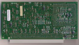
@joethezombie  Thank you for the suggestion!  The caps are all on the back of the DayStar 040 accelerator card as shown in this photo...

DayStar_PDS_Accelerator_Back.jpg

I first measured voltage across each capacitor to ensure there was no voltage (caps were indeed discharged) and then performed a Continuity check across each of the tantalum capacitors using my Fluke 8845A benchtop meter.  There were no shorts across any of the tantalum caps, which are the big black components in the photo above (light gray stripe marking the Positive side).

I then used my DER EE DE-5000 LCR meter to measure Capacitance and ESR, but the capacitance reading clearly shows that the caps are connected together at unknown points (I don't have a schematic) along with some of the tiny ceramic caps too, no doubt:

When measuring across either of the tantalum caps marked 10-16V (C46 & C28):

27uF, ESR=38Ω(@120Hz)

When measuring across any of the 4 tantalum caps marked 4.7-25 (C11, C29, C32, C49):

41uF, ESR=9Ω(@120Hz)


techknight

Well-known member
LOL. Yep, I am pretty daft. Didn't pick up on it.  Anyways regarding the topic, I have blown up so much electronics over the years its not even funny especially when I was younger. I never take it personal anymore otherwise it will eat you alive. Not to mention the time I tried to stick a Nubus ethernet card into an SE, Backwards. It fit, but did it work? um.... you dont want to know. 

ESD, reverse polarity, experimenting, you name it. I always just chalk it up "in the name of science" for me when I do it experimenting or attempting to repair something. 

My "E.B Club" is probably larger than the participating members in this thread combined. 

As for the card, its likely the IC is dead. As Bolle had mentioned the different voltages getting applied to logic lines, Easiest thing to do is grab a DMM and check those lines on the card between VCC and Ground, it likely shorted one of them out to one of the voltage rails. Either VCC or ground. Especially if you hold up one of the /SIZ lines, it'll fail to boot. 

The power supply has no PTCs in it, not these days. One of the voltages rails was grounded by the mistake, and it tripped the built-in overcurrent protection. Once the comparator latches the D-Flop, there is a capacitor that has to discharge before it clears the latched state, This is all built into the SMPS controller IC. As long as voltage is applied, the timing capacitor stays charged, and the D-Flop stays latched. So before the timing capacitor can discharge, the main input filter capacitor has to discharge, and since there is essentially no load, this can take a long long time. 

All it takes is a fraction of a microsecond to damage a semiconductor. MUCH shorter than the duration at which the protection will latch in, Trust me. That single pulse from the power supply that is outside the specs is enough to blow the junctions of logic gates. 

you drive a transistor above or below its maximum limits it will damage it. Most datasheets have an "Absolute Maximum Ratings" section you can take a peek at which shows the limits, as well as the duration of what can happen before a chip cannot tolerate it, Just to help gauge things into perspective. 

 
Last edited by a moderator:

JDW

Well-known member
As for the card, its likely the IC is dead. As Bolle had mentioned the different voltages getting applied to logic lines, Easiest thing to do is grab a DMM and check those lines on the card between VCC and Ground, it likely shorted one of them out to one of the voltage rails. Either VCC or ground. Especially if you hold up one of the /SIZ lines, it'll fail to boot. 
@techknight Please accept my sincere thanks for your helpful and detailed reply!  

Before I proceed with your recommended DMM testing of the DayStar accelerator card, could you please explain what you mean by "/SIZ lines"?  

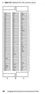
Also, I found a SE/30 PDS Pinout Chart, but would you or anyone else know of a similar pinout chart for the Cache connector?  I need that to know the pinouts of the card to more precisely know what to test on the Daystar card's connector.

Many thanks.


JDW

Well-known member
@Bolle Thank you for the Cache connector diagram.  But in addition to wanting to know the hidden meaning of "/SIZ lines" from TechKnight, I now would like to know the secret handshake that gains me access to "DCaDftMF" and its elusive meaning.  8-o

Seriously, folks.  My feeble brain got the meaning of "E.B. Club" in a split second, but "/SIZ lines" and "DCaDftMF" are a bit deep for me!  Please have mercy!


joethezombie

Well-known member
The CACHE slot connector has two signals, SIZ0 and SIZ1 on pins C40 and C39.  But on the PDS connector, pin C40 is +12V.

So, during the EB, instead of the low current signal SIZ0 reaching the accelerator, it was supplied with high current +12V.  

The DCaDftMF stands for Designing Cards and Drivers for the Macintosh Family.  It contains all the pinouts and technical information for the Macintosh family of computers.   You can google the title and find a pdf version online.


JDW

Well-known member
I recreated the Cache Connector diagram for easier viewing (vector art):

View attachment Cache_Connector_IIci_SE30-TSadapter.pdf

Pages 387-393 of Designing Cards and Drivers for the Macintosh Family make no mention of the voltage level of Vcc, nor does a keyword search for "Vcc" in that same PDF yield any results.  Does "Vcc" (see location C-4 on the Cache Connector) mean +5V?  If Vcc=+5V then what differentiates "Vcc" from the other Cache Connector pins explicitly marked "+5V"?

Thanks.


JDW

Well-known member
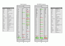
I still want to know what "Vcc" is on the Cache connector, but for now I've created a side-by-side of the two connectors, highlighting voltages and grounds for clarity and easy comparison.  Here's the GIF version:

Cache_and_PDS_Compared.gif

And here's the vector (keyword searchable) PDF version: View attachment Cache_and_PDS_Compared.pdf

We can see the Cache connector on the left has Vcc and +5V power lines in column C, which if connected to the SE/30's PDS connector (as I did in my epic blunder), the cache card (my Daystar accelerator) would try to pull power from the signal lines shown in column C on the PDS connector.  But since my SE/30 motherboard and PDS connector work with my DiiMO and MacCon Ethernet just fine in my testing, I will assume that none of those signal lines were damaged by the Daystar card trying to pull excessive power from them.

The SE/30 PDS connector supplies 5V power and ground at various points in rows 1-37, but those would appear merely as signals, causing no harm.

As @Bolle and later @techknight and @joethezombie point out, the area of observation and concern are rows 39-40.  Specifically, we have the following analysis:

  • 39-B: +5V to GND. GND is supplied by the PDS Connector, but since the Cache card could not obtain a working 5V (with sufficient current), I assume no short occurred here.
  • 40-A: -12V (neg. voltage) shorts to GND. Bolle suspects this should NOT have caused damage, and since my SE/30 has since tested working, such would appear to confirm it is OK.
  • 40-B: POTENTIAL PROBLEM! -5V (neg. voltage) is applied to the Daystar card's CACHE signal. Not sure where CACHE leads to on the Daystar card, but I would suspect -5V would post a serious problem on all the signal I/O pins it touched, which expect voltages between 0 and 5V only.
  • 40-C: SERIOUS PROBLEM! +12V gets applied to SIZ0, as has been mentioned.  The problem is the lack of schematic for the Daystar to know what was fried along that path.  And since I have no means to test a 68040 CPU, I cannot determine if the CPU alone is dead, or other chips on the board.  If any of you do have the means to test the CPU, perhaps we can talk?
 
Top