tfelder1
New member
Sharing my experience with replacing CCFL tubes in an Apple Cinema Display 20", model number A1030...
My acrylic Cinema Display had a broken top backlight bulb, but was otherwise in good shape so I bought some LED backlight strips from Ali that I thought might work as replacements. The CCFL tubes can be found on the web, but are very expensive, and mostly out of stock. Here is the link to the product I bought. You may find them elsewhere, ebay, etc. I'm pretty sure these kits all ship with the same driver board; just make sure the LED-strip is the right length: unaffiliated product link
There are a few things to note with this mod:

CCFL-starter board. Get rid of this.

Warning-indicator LED – disconnect this. Alternatively you could find constant 5V somewhere or use a buck converter to keep it "always on" when the display is powered on. There is also a green LED on the controller board which comes on when there is an active video signal. It should be possible to solder the power/status LED on the bezel to the pads of this internal LED to get external indication of video/power while bypassing the CCFL check, which makes the LED blink annoyingly. I'm fine with it off all the time.

This is the pinout of connector J7. The orange arrow is the brightness control PWM signal, which I did not end up using.

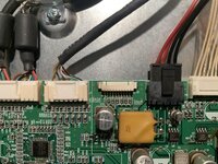
This is the actual connector on the opposite side of the board. Note it says J2 in that area. This is J7 not J2.

The LCD has a black plastic frame with latches. Stick a flathead screwdriver in there and it will come lose.

LCD Panel fully disassembled with diffusor layers visible

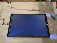
Testing backlight with bench power supply. Illumination is even, some spill from the corners. This remains ever so slightly visible through the front bezel of the re-assembled display, but not a problem for me. You would need to put some putty into the aluminium bracket to avoid this.


Misfits. Rebels. No problem.

Softbox. No LCD element yet.

The LCD has a bunch of flex connectors that fold over the backlight assembly and another thin one on the side


LCD added, plastic frame snapped back on. Backlight is relatively even. The spill in the corners is no longer visible after full assembly and with active video input. Make sure to re-attach the little flipwits in the corners.


The outermost frame on the LCD assembly is made of aluminium and has the LCD controller board attached to the back. This mounts to the plastic outer casing.


Careful not to tear these flex ribbons with the 90° bends in them. Stick them back down with the mounting tape. I reused the existing strips.


The power cables to the LED strips come out the same hole as the old ones for the CCFL-tubes. Make sure you know which side of the display you're looking at when re-assembling. It can be hard to tell.

Reattach the two connectors going to the LCD element from the controller board. First test with a video signal, still running backlight off the bench PSU.


Grab the 25V from J7 which originally powered the CCFL-starters. Try BRT_CTL is you like. I don't have any separate PWM-signal-generator circuits here and this built-in one seemed unstable on my unit. YMMV.

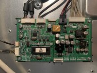
This is the back of the LCD with the new LED driver board installed where the CCFL starter / power board used to be. You can mount it there, but make sure to add some plastic, both above and below the LED-driver board as mine ended up shorting out on something.

Reassemble Display and place with my other vintage Apple stuff on my vintage Apple-stuff-desk...


My acrylic Cinema Display had a broken top backlight bulb, but was otherwise in good shape so I bought some LED backlight strips from Ali that I thought might work as replacements. The CCFL tubes can be found on the web, but are very expensive, and mostly out of stock. Here is the link to the product I bought. You may find them elsewhere, ebay, etc. I'm pretty sure these kits all ship with the same driver board; just make sure the LED-strip is the right length: unaffiliated product link
There are a few things to note with this mod:
- The color temperature of the LEDs is blue-ish; you can compensate a little bit by running the Calibration Utility after you're done; it will likely never be a color accurate monitor, but it looks great
- Apparent brightness is slightly higher
- There is a PWM signal on the internal logic board to control the brightness. There are some pictures below and attaching the driver board to a specific pin on the internal controller logic-board does make the software brightness control in System Preferences work – but it also made my display flicker … so I ended up disconnecting it; this results in constant maximum-brightness output. Some people doing similar mods on YouTube mention that this makes the LED-strips produce more heat. So far it is has not caused any problems.
- The internal controller will still think that there is a problem with the backlight tubes and the LED on the bezel (bottom-right) will be flashing; I don't know how to work around this and have disconnected the warning LED on my display because it's annoying
- With the way I attached the driver board, I ended up shorting it; probably because the back of the LCD, the shielding/cage, inner aluminium cover and generally everything in that area is conductive and there are exposed pins on the back of the LED driver board; don't make the same mistake... I had to replace my board and added some plastic insulation the second time, pulled from from the original CCFL-starter board; it's fine now
- The LCD panel itself must be taken apart into multiple layers of diffusors, the acrylic panel (about 8mm) and LCD unit itself (only 1-2mm thick); this is a bit tricky and also scary. The layers are not perfectly cut to size – this does not matter. The black plastic frame will keep them in place – just make sure the LCD and diffusor sheets overlap. If you create a crease in the plastic sheets, this will be visible. If you have excessive dust between the sheets, this may be visible. Keep things clean and dust the layers, but don't fret – I was really worried things would be out of alignment that dust from the air would result in speckles, splotches, artefacts,... but it's all fine. I used microfibre cloth and alcohol to wipe the layers.
- The connector on the internal PCB that we need to splice into actually has a pinout diagram printed on the PCB. However, it's not clear that this is actually connector J7
CCFL-starter board. Get rid of this.
Warning-indicator LED – disconnect this. Alternatively you could find constant 5V somewhere or use a buck converter to keep it "always on" when the display is powered on. There is also a green LED on the controller board which comes on when there is an active video signal. It should be possible to solder the power/status LED on the bezel to the pads of this internal LED to get external indication of video/power while bypassing the CCFL check, which makes the LED blink annoyingly. I'm fine with it off all the time.
This is the pinout of connector J7. The orange arrow is the brightness control PWM signal, which I did not end up using.
This is the actual connector on the opposite side of the board. Note it says J2 in that area. This is J7 not J2.
The LCD has a black plastic frame with latches. Stick a flathead screwdriver in there and it will come lose.
LCD Panel fully disassembled with diffusor layers visible
Testing backlight with bench power supply. Illumination is even, some spill from the corners. This remains ever so slightly visible through the front bezel of the re-assembled display, but not a problem for me. You would need to put some putty into the aluminium bracket to avoid this.
Misfits. Rebels. No problem.
Softbox. No LCD element yet.
The LCD has a bunch of flex connectors that fold over the backlight assembly and another thin one on the side
LCD added, plastic frame snapped back on. Backlight is relatively even. The spill in the corners is no longer visible after full assembly and with active video input. Make sure to re-attach the little flipwits in the corners.
The outermost frame on the LCD assembly is made of aluminium and has the LCD controller board attached to the back. This mounts to the plastic outer casing.
Careful not to tear these flex ribbons with the 90° bends in them. Stick them back down with the mounting tape. I reused the existing strips.
The power cables to the LED strips come out the same hole as the old ones for the CCFL-tubes. Make sure you know which side of the display you're looking at when re-assembling. It can be hard to tell.
Reattach the two connectors going to the LCD element from the controller board. First test with a video signal, still running backlight off the bench PSU.
Grab the 25V from J7 which originally powered the CCFL-starters. Try BRT_CTL is you like. I don't have any separate PWM-signal-generator circuits here and this built-in one seemed unstable on my unit. YMMV.
This is the back of the LCD with the new LED driver board installed where the CCFL starter / power board used to be. You can mount it there, but make sure to add some plastic, both above and below the LED-driver board as mine ended up shorting out on something.
Reassemble Display and place with my other vintage Apple stuff on my vintage Apple-stuff-desk...