• Updated 2023-07-12: Hello, Guest! Welcome back, and be sure to check out this follow-up post about our outage a week or so ago.

PowerBook 540c Replace CCFL with LED

AEChadwick

Well-known member
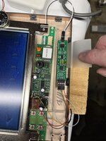
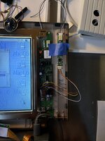
confronted with fading light behind an otherwise lovely active-matrix screen, i am attempting to replace the the CCFL with an off-the-shelf LED strip. I have done this same mod a couple times; i finally obtained a spare 500-series inverter board upon which I could practice.

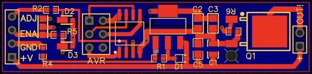
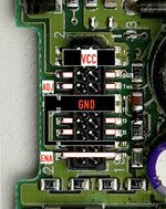
I could not find any kind of schematic online, so this was another poke-things-and-click-around exercise. GND and VCC were pretty easy; i think I found ENA and ADJ. (Contrast does screen stuff not related to the backlight.)

two problems...


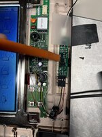
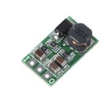
The LED strip does not get nearly bright enough. Maybe the still present CCFL-backlight-circuitry is pulling too much power away from [currently parasitic] LED controller board? The board is getting 16v which should power everything correctly; in fact, the LED strip flashes to full brightness at startup and shutdown. Maybe I can cut away the rest of the board...? (it is not a matter of placement, the strip is shooting straight down into the glass and it did the same dimness stuff when laying beside the screen during testing.)

More frustrating: like on some other versions of this mod, the brightness is “reversed”--the LED strip is brightest when set to lowest, and in its currently underpowered state it fades completely to black at barely “half-bright.”

I will continue to poke around; i welcome any insight.

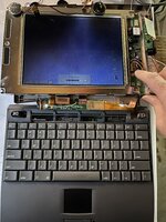
(*don’t judge this screen, it’s a 520c screen with some problems, I’m just using it so i don't wreck the good 540c screen)

PB500_InverterBoard.png
 

Attachments

  • Wires.jpeg
    Wires.jpeg
    1.7 MB · Views: 41
  • Works.jpeg
    Works.jpeg
    1.9 MB · Views: 36
  • LivingBackwards.MOV
    19.9 MB

alexGS

Well-known member
The brightness control for the replacement driver probably expects a voltage 0-5V? While the PowerBook’s control is probably producing a constant-voltage, PWM signal. Maybe tie it to 5V, perhaps using a voltage divider pair of resistors from your VCC.

Perhaps also see this post in the thread 'Duo 280c LED Backlight'
https://68kmla.org/bb/index.php?threads/duo-280c-led-backlight.43530/post-474884
The chip on your LED driver might support inverse dimming?

Personally, I think it’s worth avoiding LEDs. I bought a couple of LED backlight kits from Singapore with their own driver board and two strips each. They turned out to be terrible - not just the blueish colour (ruined the onscreen colours), the LEDs were driven way too hard and some in the strip were brighter than others (I’m guessing there were variations in resistance/forward voltage) - the bright ones burned out after about half an hour of use. The rest died over the next couple of weeks, becoming very dim. The supplier didn’t want to know, of course :)

I took apart a broken LCD all-in-one PC and removed the LED strip from that. I was not able to reduce the length of the strip without knocking out the series circuit, but it didn’t matter anyway because even when it did work, the LEDs were too separated - not diffuse enough to work well as a backlight.

Finally, I tried using a general-use continuous LED strip (COB LEDs, 48 in each segment that would normally have three LEDs in a standard strip) but this time the results were too dim and yellow compared to the original CCFL in the passive-matrix colour display that I was attempting to improve.

I would replace a CCFL tube with another CCFL tube instead. There are plenty available on AliExpress in different lengths. Bit more expensive than LEDs but worth it for the better colour rendering, I reckon.
 
Last edited:

AEChadwick

Well-known member
looking around for ideas, i found an old instructable by a dude that made his own controller board. The board uses software to convert the analog signal to PWM for the LED—i think the code could flip the reversed signal.

I am not skilled at electronics, but i know how to make things. I put the schematic into EasyEDA to generate some quick simple boards.

I had to make a couple choices to use current in-stock items... the specs read the same (to me), but i might have chosen badly because the boards almost work.

the board takes in 16v, sends 5v to the ATTiny85, and outputs from 2v (dark) to 16v (brightest). The brightness control works (it is still reversed, i wanted the board to work before i changed any code). But: the LEDs never get fully bright. Plus there is an occasional flicker. Maybe some component is out of spec or powered wrong.

posting here as progress. I would love if someone with actual electronic skill had a minute to review, like @Bolle @cheesestraws

there are no stakes & no deadline here, i'm just tinkering.


backlight_controller.png
 

Attachments

  • backlight_controller.txt
    8.4 KB · Views: 3
  • in_situ.jpeg
    in_situ.jpeg
    2.2 MB · Views: 22
  • flicker.mov
    10 MB
  • darker.jpeg
    darker.jpeg
    1.7 MB · Views: 23
  • brightest.jpeg
    brightest.jpeg
    1.6 MB · Views: 20
  • backlight_controller.pdf
    39.6 KB · Views: 3

AEChadwick

Well-known member
i corrected a few flaws and produced a second board; REV1 has a better traces all around. The improved power rail revealed 16v was too much for the LED strip; the appearance of magic smoke led me to get a little step-down converter, turning the PowerBook’s 16v into 9v. The resulting 9v powers the board and LED correctly; the board injects a PWM signal to control the LED brightness. I changed a couple lines in the software to invert the map, and now LED brightness goes up and down correctly...

215 // Invert the mapping by subtracting from the maximum value 216 return(outMax - (x - inMin) * (outMax - outMin) / (inMax - inMin));

However there is still a terrible flicker. The flicker is definitely produced by something in the incoming signal—if i set the software to a specific brightness, like brightnessLevel = 128 the screen is rock solid.

So the Attiny is reading things weird... maybe the 5V Zener at D2 was pulling the ADJ signal wonky? I took that diode off the board, no change.

(My multimeter shows the voltage staying constant, but maybe it's just not sensitive enough.)

i will poke around more.

View attachment Inversion works.mov
 

Attachments

  • Backlight Controller REV1.jpg
    Backlight Controller REV1.jpg
    182 KB · Views: 15
  • Backlight Controller REV1.pdf
    39.6 KB · Views: 0
  • boards_in_place.jpeg
    boards_in_place.jpeg
    3.6 MB · Views: 30
  • PB_CCFL_LED_controller_REV1.txt
    8.6 KB · Views: 0

AEChadwick

Well-known member
after a long, deep dive into "how to manipulate a PWM signal for Dummies," i went back to the original board. Most of these LED controller boards are just the DF6113 "example circuit" with a voltage converter on the output.

I spent a lot of time trying to figure out the DF6113 and realized my biggest problem was a bad screen and too much voltage. I re-did the wiring with a fresh controller and a known, working 540c screen... and everything worked great. Lord have mercy.

So, here is the mod for the PowerBook 500-series.

I soldered wires to the inverter board at the interconnect cable connector. I removed the big transformer because it was not needed, and i removed the two transistors immediately below it to make a place to mount the controller board. The powerbook sends 16V to the inverter board, and for some reason that comes out of the controller unaltered (i burnt out a couple strips before realizing that...); I used a little buck converter to push that 16V down to 9V, and hid it in the well where the CCFL transformer had been. The LED strip is wedged in place with a strip of ABS.

it works perfectly, and really does get darker and brighter... the video doesn't do justice because the iPhone adjusts too quickly for the low light. But it works and looks really sharp.


520c_inverter.jpeg
 

Attachments

  • 520c_inverter.jpg
    520c_inverter.jpg
    203 KB · Views: 25
  • 520c_Brite.jpeg
    520c_Brite.jpeg
    3.6 MB · Views: 25
  • 520c.mov
    17.3 MB
  • buck.jpg
    buck.jpg
    33.5 KB · Views: 22
Last edited:

alexGS

Well-known member
Yes, thank you for taking the time to update us!

So to recap; the board that comes with an LED backlight kit isn’t usable because the brightness wasn’t sufficient or the control was inverted? I think that’s why you’ve made your own? Just curious whether a standard board can be used with a buck converter.
 

AEChadwick

Well-known member
So to recap; the board that comes with an LED backlight kit isn’t usable because the brightness wasn’t sufficient or the control was inverted? I think that’s why you’ve made your own? Just curious whether a standard board can be used with a buck converter.

the board that comes with the LED controller kit is usable and works great when used with the little buck converter. The PowerBook’s signal is not inverted and needs no modifications; just wire to the points shown.

the adventure with my little custom board was a fun digression that might come in handy later; it mostly led me to explore Analog vs PWM signals in relative depth, and test different voltages and things. the initial signal weirdness was probably accidental reversing of ADJ / ENA, plus that deadly 16V into the LED strip.
 

Iesca

Well-known member
Now, what would be nice, is finding a modern LCD solution for these and other PowerBooks. My own 540c's display is near-perfect, save for a couple very minor spots that have been there since I first got it in the early 2000s more than 20 years ago (eep!), but many are not so lucky...
 
Top