• Updated 2023-07-12: Hello, Guest! Welcome back, and be sure to check out this follow-up post about our outage a week or so ago.

Prototype ROMS, question.

unity

Well-known member
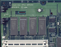
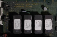
This might be my only system on hand with prototype ROMs. So I can not tell if this are in the correct order. I assume they are, but the machine powers up and does nothing. Before I re-cap, I want to make sure these are correct.

My only guess is:

LL - low low

ML - middle low

MH - middle high

HH - high high

Other than those identifiers, there are no differences externally. By the way, I did clean the board since to wash off any cap goo, etc. And I have tried good power supplies. Odds are I need a re-cap.
$_57-3.JPG

 
Last edited by a moderator:

trag

Well-known member
Is that the order they were in when you got it?  Given the markings, that seems to make sense, although there's no assurance that the physical location of the sockets corresponds to the range of data pins that it covers.    On the bright side, there's only 24 possible combinations in which you could install them.  :)

Alternatively, find a component for which you know the data pin arrangement (the CPU, or a ROM SIMM socket, if present) and check continuity between the ROM data pins and the known device.   That'll tell you which of the four ranges each socket corrsponds to.   Then if the markings on the chips are logical, the arrangement should be certain.

I like the HH, MH, ML and LL nomenclature.   Later, Apple started using HH, HL, LH and LL, which is confusing as heck, unless one knows that the more significant label takes precedence and most significant is on the left and least significant is on the right.


unity

Well-known member
Yes, IIcx. Not sure if checking pins would work since they are EPROM - they would all have the same pin-outs, no?


trag

Well-known member
Yes, IIcx. Not sure if checking pins would work since they are EPROM - they would all have the same pin-outs, no?
Yes, but what you have is four EPROMs with 8 [0:7] data pins each and a computer system with 32 [0:31] data pins total.   Each chip fills one of the following ranges of data pins: 

[0:7]

[8:15]

[16:23]

[24:31]

On the CPU and the ROM SIMM socket (if present, does the IIcx have one?) you can identify all 32 pins.   I.e. pinout listing are available which will tell  you whether a data pin on the CPU (or in the ROM socket) falls within the first, second, third or fourth range.

Trace that data pin from the CPU or ROM SIMM socket to the ROM chip sockets.   If the pin for a ROM chip socket connects to a pin on the CPU that is numbered from 0 to 7 (or 1 to 8 depending on indexing) then that ROM chip socket is for the LL ROM chip.   Simiilarly for a pin which connects to 24 to 31 in the CPU socket.   The ROM chip socket with that pin must be for the HH ROM chip.

Or just get someone to send you a photo of a IIcx with ROMs properly installed, assuming that production ROMs have meaningful labels.

 
Last edited by a moderator:

Elfen

Well-known member
Its hard to see on Unity's image, but the area above his board is marked as his chips - HH, MH, ML and LL; as is the area above the chips on Uniserver's. So they match.


unity

Well-known member
Sweet - yes Uni that will work. I honestly never noticed those marking on my other IIcx boards! So yes, that helps a ton. I feel better now.

By the way - the caps on this board are not polarized the same way as a production board, all reversed - at least the barrel caps. I did not check the tiny tin trash cans yet.

Well onto a re-cap and see what happens. At least it powers up and stays on, just no chime or video.

 
Top