• Updated 2023-07-12: Hello, Guest! Welcome back, and be sure to check out this follow-up post about our outage a week or so ago.

Programmatically (in C) send MIDI out signal from modem port, SE/30

Mu0n

Well-known member
I assembled a small breaboard midi-in circuit, powered by a bench supply providing 5V, according to this well known circuit:
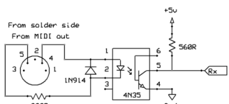
1720010651204.png

which looks like this (I had optoisolator H11 chips from previous projects)
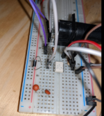
1720010686766.png

and just to prove it works, I plugged my pocketmac midi out cable to this breadboard while cubase was playing a tune, and I checked an oscilloscope set to decode RS232*, 31250 bps, 1 stop bit and I was able to single shot capture a bunch of midi commands, here's a Note On set of three bytes on channel 9, but since its velocity is 00, it's probably interpreted as a Note Off:
(*I know the mac serial or midi isn't RS232, but it's the closest setting on my scope I can use, and you can modify it to oblivion with the other parameters anyway)
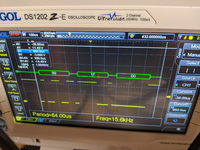
1720010787254.png


For the time being, I'm going through the myriads of suggestions and I've tested a bunch, nothing was conclusive yet. I'm trying to be careful not going into many rabbit holes of technical knowledge that I barely understand, so my first real step is keeping the C code I posted above, but doing small incremental changes. Here's what happened since I last posted it:

1) I added a scanf routine so that I can control when to send a note to the serial (modem) port, it's an ANSI console application, so I'm getting easy text feedback on error messages and whatnot, and can let myself control when to do what so I can be ready with my oscilloscope and prep it for single shot captures.

2) I tried to modify the MyConfigurePort to take in value '1' in its parameters, since it'd get me to 38,400 bps. I don't get anything on the scope that's valid.
C:
void MyConfigureThePort(void)
    {
    const int kConfigParam = 1+data8+noParity+stop10;
    char myParam = 0x40;
    
    gOSErr = SerReset(gOutputRefNum, kConfigParam);
    
    if(gOSErr == noErr)
        {
        printf("port configuration successful\n");
        }
    else printf("port configuration unsuccesful, code=%d \n",gOSErr);
    
    }

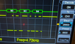
3) Right after the MyConfigurePort function, I added another one which uses Control and csCode 16 and I've mainly played with 0x40 as the parameter to send, which sets bit 6 to 1, supposedly to enable external clock. Is there anything else that has to be done? It doesn't seem to be enough, because this is what I get on the scope - not large enough for 3 bytes that I send (0x90, 0x3C, 0x64; each byte has to be 320 us) and the decoding fails to pick anything:

4) that same step 3 can now be activated with my typing - I type 2 hex characters and that's the hex value that'll be sent with a Control, as such:
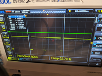

C:
void TweakClock(char param)
    {
    //Tie the clock to external control
   
    gOSErr = Control(gOutputRefNum, 16, &param);
    if(gOSErr == noErr)
        {
        printf("external clock control successful\n");
        }
    else printf("external clock control  unsuccesful, code=%d \n",gOSErr);
    }

1720011165999.png
 

Mu0n

Well-known member
I also tried keeping the default clock, setting the SerReset parameter like above but adding '2' instead of '1' to get 28,800 instead of 38,400 and my scope is detecting: 0xC6 0x22 instead of 0x90 0x3C 0x64
 

ymk

Well-known member
The circuit you posted describes both the sending and receiving device.

As the sender, you only need to worry about limiting current to the receiver's optoisolator.

The only component you need is the resistor at the bottom of the schematic. 4.7K is a safe starting value.
 
Last edited:

Mu0n

Well-known member
The circuit you posted describes both the sending and receiving device.

As the sender, you only need to worry about limiting current to the receiver's optoisolator.

The only component you need is the resistor at the bottom of the schematic. 4.7K is a safe starting value.

SE/30 modem port -> pocket Mac, midi out -> my breadboard midi in connector, current limited loop

Other side of H11: 5V and GND are provided and a 1k resistor acts as load that I'm probing.

I don't understand what you're suggesting I do differently since my use case under normal conditions from Cubase prove that I can detect MIDi bytes that make sense.
 
Last edited:

ymk

Well-known member
Ok, so the breadboard is the receiver. Measuring voltage directly from one of the Pocket Mac pins would also work.

If what @joevt posted is accurate, you can drive the SC-88 or other MIDI device directly from the Mac's serial port with just a resistor in between.

I didn't know if your goal was to keep the Pocket Mac or not.
 

Mu0n

Well-known member
Getting MIDI across to my sound modules I have achieved, no problem, for years. However, only through commercially developped software that I open and execute as an end-user (Cubase, Space Quest III, Master Tracks Pro 4, etc).

The goal is to recreate what they did through my own C routines. If I can just begin with the baby step of sending a properly formatted channel 1 middle C note, pushed through the serial port, at the right cadence, I'd be well on my way for bigger and brighter things.
 
Last edited:

ymk

Well-known member
If I can just begin with the baby step of sending a properly formatted channel 1 middle C note, pushed through the serial port, at the right cadence, I'd be well on my way for bigger and brighter things.

Then you might try the clockMode x1 method joevt described (with or without the Pocket Mac) and ignore the external clock.
 

joevt

Well-known member
2) I tried to modify the MyConfigurePort to take in value '1' in its parameters, since it'd get me to 38,400 bps. I don't get anything on the scope that's valid.
Do you get something valid if you change the scope from 31250 to 38400 bps?

When I search for 31250 in this thread using Command-F in Safari, it finds the 31250 text in your scope picture which I think is kind of amazing. It's able to find most of the text in the picture (except not the text on the beige plastic of the scope?).

3) Right after the MyConfigurePort function, I added another one which uses Control and csCode 16 and I've mainly played with 0x40 as the parameter to send, which sets bit 6 to 1, supposedly to enable external clock. Is there anything else that has to be done? It doesn't seem to be enough, because this is what I get on the scope - not large enough for 3 bytes that I send (0x90, 0x3C, 0x64; each byte has to be 320 us) and the decoding fails to pick anything:

4) that same step 3 can now be activated with my typing - I type 2 hex characters and that's the hex value that'll be sent with a Control, as such:
Did you check the HSKi pin on the Mac to make sure it's receiving a clock? The clock has to have negative and positive voltage.
Can you show the clock on the scope?

Here's what those bytes should look like separately:
Code:
0x90 = ----------_____-__-----------
0x3C = ----------___----__----------
0x64 = ----------___-__--_----------

And together:
Code:
0x90 0x3C 0x64 = ----------_____-__--___----__-___-__--_---------------------

Maybe try some other interesting patterns:
Code:
0x55 = ----------_-_-_-_-_----------
0x00 = ----------_________----------
0xFF = ----------_------------------

Are you sending the bytes out one at a time, or all three at once? There's a lot more idle time than there should be, but your first scope picture doesn't show any extra idle time.

C:
void TweakClock(char param)
    {
    //Tie the clock to external control
   
    gOSErr = Control(gOutputRefNum, 16, &param);
    if(gOSErr == noErr)
        {
        printf("external clock control successful\n");
        }
    else printf("external clock control  unsuccesful, code=%d \n",gOSErr);
    }
Should print the param value.

I also tried keeping the default clock, setting the SerReset parameter like above but adding '2' instead of '1' to get 28,800 instead of 38,400 and my scope is detecting: 0xC6 0x22 instead of 0x90 0x3C 0x64
Does your scope detect it correctly if you set it to 28800 bps?

I believe 28800 and 38400 are out of range for 31250 bps:
Code:
      start bit 0 bit 1 bit 2 bit 3 bit 4 bit 5 bit 6 bit 7 stop
_____       _____ _____ _____ _____ _____ _____ _____ _____ _____ ______________________
     \_____X_____X_____X_____X_____X_____X_____X_____X_____X
     
     0    100   200   300   400   500   600   700   800   900    bit transition times
       50    150   250   350   450   550   650   750   850       bit sample times

Assume clock period = 100. The last bit in an 8N1 packet begins at time 800 and ends at time 900. The last bit should be tested at 8.5 clock periods. Therefore:
1) minimum clock period = 800 / 8.5 = 94.12
2) maximum clock period = 900 / 8.5 = 105.88
clock period range = ±5.88%

31250 * (1-0.0588) = 29412.5
31250 * 1.0588 = 33087.5

If expecting 31250 bps, then the allowable range is between 29412.5 and 33087.5 bps. That assumes there's no improved clock recovery after the beginning of the start bit. The clock could be recovered at any transition though. This range is true if there are no other clock transitions, (for example: a 0x00 is being transmitted).
 

joevt

Well-known member
Code:
baud=31250
for ((i = 0; i < 8; i++)) ; do
	echo $i: $((baud * (i*2 + 2) / (i*2 + 3) )) $((baud * (i*2 + 4) / (i*2 + 3) ))
done

0: 20833 41666
1: 25000 37500
2: 26785 35714
3: 27777 34722
4: 28409 34090
5: 28846 33653
6: 29166 33333
7: 29411 33088

So the scope set to 31250 bps might be able to get the first 5 bits of a 28800 bps stream but your scope only got the first two bits correct. Maybe there's something wrong with my math. Those numbers are a best case range. The range must be shortened to account for the rise and fall time. There may be other issues. The sample time of the scope might not be exactly in the middle of a 31250 bps bit. The output of the Mac might not be exactly 28800 bps.
 

Mu0n

Well-known member
Do you get something valid if you change the scope from 31250 to 38400 bps?

Good idea. It gets my bytes correctly at 38,400 set in both the mac SCC through SerReset and on the scope, using these 2 lines:
C:
    const int kConfigParam = 1+data8+noParity+stop10;
    gOSErr = SerReset(gOutputRefNum, kConfigParam);

1720183824833.png

Did you check the HSKi pin on the Mac to make sure it's receiving a clock? The clock has to have negative and positive voltage.
Can you show the clock on the scope?
I have no easy way to probe these lines. My small MIDI interface box can't be opened without permanent damage, and I don't have a breakout female socket for mac serial. If things get dire, I could keep my SE/30's case opened and use my chip hook cables somewhere, but I'll leave that for later for now.

Are you sending the bytes out one at a time, or all three at once? There's a lot more idle time than there should be, but your first scope picture doesn't show any extra idle time.

For test purposes, I'm sending a 3 byte array, 0x90, 0x3C, 0x64. I posted the MySendMessage function that I'm using early in the thread, here it is again for convenience:

C:
void MySendMessage(void)
    {
    char myMessage[3]={0x90,0x3C,0x64};
    long int myMsgLen;
    ParamBlockRec myParamBlock;
    ParmBlkPtr myPBPtr;
    
    myMsgLen=3;
    
    myParamBlock.ioParam.ioRefNum = gOutputRefNum;
    myParamBlock.ioParam.ioBuffer = myMessage;
    myParamBlock.ioParam.ioReqCount = myMsgLen;
    myParamBlock.ioParam.ioCompletion = nil;
    myParamBlock.ioParam.ioVRefNum = 0;
    myParamBlock.ioParam.ioPosMode = 0;
    myPBPtr = (ParamBlockRec *)&myParamBlock;
    
    gOSErr = PBWrite(myPBPtr, FALSE);
    if(gOSErr == noErr)
        {
        printf("sending message successful\n");
        }
    else printf("sending message unsuccesful, code=%d \n",gOSErr);
    }

Should print the param value.
I already am, here's my main function:

C:
void main()
    {
    Boolean isDone = false;
    char answer[80];
    int convNum;

    MyOpenSerialDriver();
    MyChangeInputBuffer();
    MySetHandshakeOptions();
    MyConfigureThePort();
    
    while(!isDone)
        {
        printf("tweak clock with 00 to FF + send a note; .=just a note q=quit\n");
        gets(answer);
        if(strcmp(answer,"q")==0 || strcmp(answer,"quit")==0) isDone = true;
        if(strcmp(answer,".")==0)
            {
            MySendMessage();
            
            printf("note sent\n");
            }
        else
            {
            convNum = (int)strtol(answer,NULL,16);
            printf("hex number 0x%x or %d detected \n",convNum, convNum);
            TweakClock(convNum);
            MySendMessage();
            printf("note sent\n");
            }
        if(Button()) isDone = true;
        }
        
    
    MyRestoreInputBuffer();
    MyCloseSerialDriver();
    
    ExitToShell(); //Go back to Finder
    }


Does your scope detect it correctly if you set it to 28800 bps?

I believe 28800 and 38400 are out of range for 31250 bps:

setting both mac and scope at 28,800 also works with flying colors.
1720184421993.png


To recap:

1) my scope setup has proven it can successfully detect the correct midi bytes that are being sent by the Mac at manually set speeds using the internal clock

2) I still need to force the external clock to be able to reach 31,250 bps, but what does that imply? Use 1 Control call only? Use a SerReset in conjunction with it? Change the handshake or keep it intact? Use 1 Control Call *and* force a clock divider as well? All those are poorly documented on the early days of Mac MIDI (circa 1987)
.
3) do I retrace the steps* in the asm code posted early in the thread? Do I assume this low level address is still valid on a SE/30? I'll certainly try it.

*the steps as I understand them, correct me if I'm wrong:
get the machine dependent address for the SCCWrite from the machine independant (?) low level 0x01D8 location
offset by 2 (aCtl offset for the A port = modem)
use that final address to write 11 in it to access register 11
wait 2.2 us (can use MOVE.B (SP),(SP) as in the asm code)
put 001010000 in the same spot to send a new control code, to enable external clock.
 

Mu0n

Well-known member
Can anyone verify if I'm doing what I think I'm doing?

C:
    int *addr = (int *) 0x0001DA;
    *addr = 11;
    asm { MOVE.B (SP),(SP) }
    *addr = 0x28;

this freezes my program but I still can move my mouse cursor around. When I click, even that freezes as well.
 

joevt

Well-known member
I have no easy way to probe these lines. My small MIDI interface box can't be opened without permanent damage, and I don't have a breakout female socket for mac serial. If things get dire, I could keep my SE/30's case opened and use my chip hook cables somewhere, but I'll leave that for later for now.
Use a breadboard and cables to breakout the signals. Or you can find things like this:
https://elabbay.myshopify.com/produ...male-connector-breakout-board-adapter-elabguy

For test purposes, I'm sending a 3 byte array, 0x90, 0x3C, 0x64. I posted the MySendMessage function that I'm using early in the thread, here it is again for convenience:
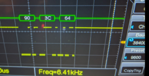
That looks fine. Just having trouble trying to decipher how the output on the scope in the second picture at #21 is supposed to represent 0x90, 0x3C, 0x64 which should look like this:
----_____-__--___----__-___-__--_----------
or like this if you add idle time for one whole byte between bytes:
----_____-__------------___----__-----------___-__--_----------
or idle time for two whole bytes between bytes:
----_____-__----------------------___----__---------------------___-__--_----------

Actually, the scope picture looks a liitle bit like the second or third. Maybe stretch the scope out horizontally so the first start bit is at the left edge of the scope and the last bit is at the right edge of the scope. Then we can see if any of the single 1 bits are more visible.

You could also try sending more interesting patterns such as 0x55, 0x55, 0x55. This pattern will emphasize how the bits are clocked. Then measure the width (in µs) of one of the bits and one of the bytes.

2) I still need to force the external clock to be able to reach 31,250 bps, but what does that imply? Use 1 Control call only? Use a SerReset in conjunction with it? Change the handshake or keep it intact? Use 1 Control Call *and* force a clock divider as well? All those are poorly documented on the early days of Mac MIDI (circa 1987)
.
3) do I retrace the steps* in the asm code posted early in the thread? Do I assume this low level address is still valid on a SE/30? I'll certainly try it.

*the steps as I understand them, correct me if I'm wrong:
get the machine dependent address for the SCCWrite from the machine independant (?) low level 0x01D8 location
offset by 2 (aCtl offset for the A port = modem)
use that final address to write 11 in it to access register 11
wait 2.2 us (can use MOVE.B (SP),(SP) as in the asm code)
put 001010000 in the same spot to send a new control code, to enable external clock.
We need to know the input clock frequency. If the input clock is 1MHz, then the default x16 divider used by the baud rate generator is incorrect. You need an x32 divider in that case.

I don't think low level addresses change in classic Mac OS.

Can anyone verify if I'm doing what I think I'm doing?

C:
    int *addr = (int *) 0x0001DA;
    *addr = 11;
    asm { MOVE.B (SP),(SP) }
    *addr = 0x28;

this freezes my program but I still can move my mouse cursor around. When I click, even that freezes as well.
int is two bytes but the registers are 1 byte.

0x1d8 is defined as SCCRd in SysEqu.h or SysEqu.a or SysEqu.p
SCCWr is 0x1DC.
LowMem.h has macros for accessing those which look like this:

C:
#define LMGetSCCRd() (* (Ptr *) 0x01D8)
#define LMGetSCCWr() (* (Ptr *) 0x01DC)

You need to load the 4 byte pointer that is at 0x1DC, then add 2 to that to access aCtl.

C:
Ptr addr = *(Ptr*)0x1DC; // there's a pointer at 0x1DC - read it
addr[2] = 4; // WR4 = register pointer set to WR4
asm { MOVE.B (SP),(SP) }
addr[2] = 0x84; // WR4 = X32, 1 stop bit, no parity
asm { MOVE.B (SP),(SP) }
addr[2] = 11; // WR0 = register pointer set to WR11
asm { MOVE.B (SP),(SP) }
addr[2] = 0x28; // WR11 = Rx and Tx clock from /TRxC Pin (HSKi on Macs)
asm { MOVE.B (SP),(SP) }

I think one of the documents in the Apple document archive describes a control code for setting MIDI mode directly.
 

joevt

Well-known member
TN1018 seems to imply that the clock input from a MIDI device is 2 MHz which would require the X64 setting to get 31250 bps. In that case, WR4 should be set to 0xC4.

The tech note describes csCode 15 for initiating an externally clocked asynchronous 8N1 mode appropriate for MIDI. See if that Control code is available with the serial driver that you are using.
 

Mu0n

Well-known member
YES, it finally works.
Thanks for the refresher tips on bytes and on how to address pointer offsets more efficiently.
Thanks for your patience and offering great guidance and some good ol' vintage docs.

As soon as I saw the scope behave well with this under 31,250, I disconnected my breadboard and reconnected my Roland SC-88ST and this is a little demo I threw:


P.S.: I used x32 as per your previous suggestion, because that's what I use in Cubase when I go into MIDI settings and it seems to work just fine.

P.S.#2: I tried to use csCode 15, but I didn't go far because I have no documentation on what the bits mean at all.
 

joevt

Well-known member
YES, it finally works.
Thanks for the refresher tips on bytes and on how to address pointer offsets more efficiently.
Thanks for your patience and offering great guidance and some good ol' vintage docs.

As soon as I saw the scope behave well with this under 31,250, I disconnected my breadboard and reconnected my Roland SC-88ST and this is a little demo I threw:

P.S.: I used x32 as per your previous suggestion, because that's what I use in Cubase when I go into MIDI settings and it seems to work just fine.

P.S.#2: I tried to use csCode 15, but I didn't go far because I have no documentation on what the bits mean at all.
TN1018 has all the info about csCode 15. It says csCode 15 takes a byte like csCode 16 does. For csCode 15, use value 0x80 for X32 mode as shown in Table 1. The bits appear to match the upper 2 bits of WR4.

I wonder if you could use SerReset to set baud constant to 57, use csCode 15 to set x1 mode, then use csCode 16 to use baud rate generator with internal clock. This might enable a 31077 - 31240 bps output mode without requiring an external clock.
 
Top