You are using an out of date browser. It may not display this or other websites correctly.
You should upgrade or use an alternative browser.
You should upgrade or use an alternative browser.
Problem with Apple Lisa 2 CPU Board - not booting
- Thread starter Greniu
- Start date
stepleton
Well-known member
With U8B, U9B, and the boot ROMs removed, the only thing left connected to most of UA9-UA16 is the CPU itself. There's nothing else on the bus.
Did you get a chance to look at my question from my last post around swapping 68000s between the good CPU board and the bad CPU board?
NOTE: Now that you've swapped U8B and U9B, don't swap 68000s yet. My question is about observations you may have made in the past.
Did you get a chance to look at my question from my last post around swapping 68000s between the good CPU board and the bad CPU board?
NOTE: Now that you've swapped U8B and U9B, don't swap 68000s yet. My question is about observations you may have made in the past.
Hi Stepleton,
I did further investigations. Configuration now is: Good board and bad board without U8B and U9B and 2 ROMS (U13D and U14D ) chips connected.
I measured all pins on U8B and U9B and they are looking pretty the same.
I measured all pins on U13D and U14D and we have a difference.
On a good board pins UD0-UD7 have an activity on U14D, on bad board they are static HIGH. The semi is with UD8-UD15 pins on U13D.
SO here maybe the clue why we had a LOW on \RESET pin earlier.
Visual difference between both boards when connected is that on good board I have a frozen image on CRT, on bad board there is black.
I have also swapped VSROM between boards - no difference.
CPU 68000 swap make no difference too. Both are ok.
stepleton
Well-known member
Thanks for the investigations, but I think we are trying to solve too many problems at once. Let's solve one problem at a time. When you try to solve more than one problem at the same time, things become a lot more complicated as multiple problems can become tangled together.
-----
So far we've made a lot of observations about the good board and the bad board. We have everything from overall behaviour (the good board works, the bad one doesn't) all the way down to recordings of the individual pins. This is a lot of information.
Despite all of our investigations, we have only one situation where we know with 100% absolute certainty that signal lines are malfunctioning. These are the non-TTL signals on UA9-UA16 on the bad CPU board when U8B and U9B are installed.
We have observed other differences between the good board and the bad board. These may or may not be evidence of problems --- we don't know yet. We only have suspicions and guesses. The difficulty for us is that these observations may be a consequence of the non-TTL signals we've been observing. There is a chance that if we eliminate the signalling problem on UA9-UA16, other problems (including problems we may not have found yet) will go away.
Let's first figure out the only situation where we know 100% that there is a problem. Then we can move on to the next problem. Let's solve one problem at a time.
-----
Standard TTL signals have two states. A "low" level is a signal between 0V and +0.8V relative to ground, and a "high" signal is between +2V and +5V.
You have measured signals on UA9-UA16 that have voltage levels around +1.8V. When a TTL chip receives inputs between +0.8V and +2V, its output behaviour is undefined. In our case, this means that the outputs of the 74F283s can be anything at all --- either the right answer (in this case, the sum of two four-bit inputs) or something entirely different.
Because 74-series TTL chips were made by many manufacturers, the response of any one IC to non-TTL inputs can differ. A Fairchild-built 74F283 may respond differently to non-TTL inputs than a part made by Toshiba or Texas Instruments or Hitachi or whoever else.
Even the same part made by the same manufacturer can respond differently to non-TTL inputs depending on its temperature! or depending on whether the Vcc is +4.8V instead of +5V! or depending on the silicon wafer that the IC was made from! or whether it was a Friday at the chip fab and the QA tech was rushing to finish their shift!
Things become difficult to understand when TTL signals stop being TTL! Our life will be easier if we get rid of this problem before moving on to the next one. Let's solve one problem at a time.
-----
If you have a TTL signal line that isn't able to achieve a "high" signal consistently, there are only a few reasons that this could be so. These are:
- The chip that's trying to emit a "high" signal (in this case, the 68000) is too weak. The parts of a chip that change the voltages on output lines --- the output drivers --- can sometimes get damaged. They may still work a bit, but they don't have the strength that they used to have when they came from the factory. If they can't raise the signal to a nice, healthy voltage, then you take your chances that the ICs that receive the signal can understand the weak, non-TTL "fuwebo glarop neep gorp" signal.
- The chip that's trying to receive signals (in this case, U8B and U9B, or also the ROMs and some other ICs for a subset of UA9-UA16) has a low-resistance current path between its input pins and ground. This means that as hard as the 68000's output drivers will try to raise the voltage level on the line to +5V, it's just too easy for the current to drain through the 74F283's input pins and for the voltage fall back down to that intermediate non-TTL level. This is a bad situation for the 68000, because it will be passing a lot of current through its output drivers as it strains to raise the voltage, which could cause damage like what I've already mentioned.
- There is something wrong with the PCB wiring itself --- the current on UA9-UA16 has another path to ground, one that's relatively low resistance. In this case too, the 68000 will be trying very hard to raise the voltage on the signal line to +5V, and it could burn itself out. This is why I recommended inspecting the board once again to see if you could find any defects.
- The circuit is actually working fine, but your measurement is misleading or broken.
-----
You have a lot of faith in your IC tester. I like IC testers too --- I'm a big fan of my own Retro Chip Tester Pro: it's a fantastic tool. Remember though what I said earlier: you can usually trust an IC tester if it says a chip is bad, but it's less trustworthy if it says a chip is good. Here are some reasons why this is so:
- Chip testers may only drive the inputs to an IC at a certain frequency. Recall that U8B and U9B are 74F-series chips, where "F" stands for "fast". The 68000 will be sending new signals to these ICs at maybe around a megahertz, and the chips will have to respond very quickly in order for the Lisa MMU to work properly. It's unlikely that your chip tester is checking for a correct response at that frequency --- and if its test for 74283 4-bit adders has to work across all 74-series families (not just F) then it must run more slowly than the speeds the IC is capable of.
- Chip testers will only ever need to drive and listen to one chip at a time. In real circuits, ICs live in a network of many other ICs, with complicated networks of "speakers" and "listeners". Chip testers therefore test an IC in close-to-ideal conditions, not real-world situations. An IC that works well in the simulated environment of the tester may still not be strong enough for an actual application.
- Most chip testers don't have anything to say about the quality of an IC's outputs. (There are a few that do.) Remember that +2V is still a valid "high" level for TTL, but if I encountered an IC that could only drive a chip tester's input up to (e.g.) +2.6V, I'd consider that part to be extremely marginal and would look for a replacement immediately. But most chip testers don't say what the voltages coming out of the chip are like.
-----
I hope all this information is useful. It's a lot, but if you take a moment to read it all, some of my suggestions from earlier may make more sense.
By now it will be no surprise that I think we should continue trying to understand why UA9-UA16 signals are not TTL. The four possibilities I listed above are all still potential factors. I have my own theories about which possibilities are most likely than others, but I'm not yet confident about them. Instead of sharing my hypotheses here, I'll be interested to hear what you think first.
What do you think might be going on with UA9-UA16? How would you test to see whether your hypothesis is correct? If you like, let me know and we can work from there.
Hi Stepleton,
Thank you very much for reply. These are very helpful advices and I really appreciate it and that you can share with me. You are amazing!
Before I reply to your answer let me explain what I did earlier today and share with you. Then I will reply to your post.
The UA9-UA16 signals that are not TTL bother me to solve the cause of it.
This turn me to the next very interesting evidence.
"I wanted to check what causes UD0-UD7 and UD8-U15 signals that they are always HIGH".
I tried to focus on the UD8-U15 signals first. I have checked (desolder) U11F and U14E, where UD8-U15 goes. I have checked them with IC tester and they are ok - at least they look like ok. So I soldered them again to the board. During comparison of measurements on both boards I noticed that good board has on chips (U11F and U14E) pin 1 activity (pulsing) with +5V floating between HIGH and LOW, but bad board has strange HIGH static signal which pulse near by +5V. Or other pin signals looks the same.
Pin 1 comes from READ (pin 9) signal from 68000 through U8C chip, so I decided to stop here.
From my observations and measurements of chip drives (mostly LS245) it looks like all of the LS245 bus chips are talking only in one direction. If their pin 1 was floating like it is on good board I would see the activity (instead of static HIGH signal on bad board).
So something is wrong here maybe U8C?
I will check the READ signal on CPU 68000 after I desolder this chip and compare.
CPU 68000 is 100% good, because I swapped and checked on the good board.
Hi Stepleton,
Thank you very much for reply. These are very helpful advices and I really appreciate it and that you can share with me. You are amazing!
Before I reply to your answer let me explain what I did earlier today and share with you. Then I will reply to your post.
The UA9-UA16 signals that are not TTL bother me to solve the cause of it. We have configuration with no F283 (U8B and U9B) inserted and no ROMs.
This turn me to the next very interesting evidence.
"I wanted to check what causes UD0-UD7 and UD8-U15 signals that they are always HIGH".
I tried to focus on the UD8-U15 signals first. I have checked (desolder) U11F and U14E, where UD8-U15 goes. I have checked them with IC tester and they are ok - at least they look like ok. So I soldered them again to the board. During comparison of measurements on both boards I noticed that good board has on chips (U11F and U14E) pin 1 activity (pulsing) with +5V floating between HIGH and LOW, but bad board has strange HIGH static signal +5V.
Pin 1 comes from READ (pin 9) signal from 68000 through U8C chip, so I decided to stop here.
From my observations and measurements of chip drives (mostly LS245) it looks like all of the LS245 bus chips are talking only in one direction. If their pin 1 was floating like it is on good board I would see the activity (instead of static HIGH signal on bad board).
So something is wrong here maybe U8C?
Hi stepleton. You wrote:
I installed good board CPU 68000 to the bad board and checked UA9-UA16 once again.
The situation with pins values is the same, but I verified that I pasted wrong image in my post regarding
"RESET PIN 18 on CPU (CH1) and PIN 11 UA12 (CH2) on U8B".
It should be "RESET PIN 18 on CPU (CH1) and PIN 11 UA16 (CH2) on U9B" and the values are like below:
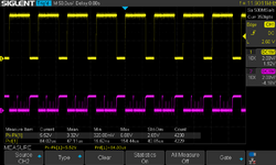
I appologize for that.To man pictures and hurry. It looks like we have still UA16 not good TTL, even CPU is swapped between boards. Thank you so much for any help.
From what you've written: when you installed the 68000 from the good CPU board into the bad CPU board, it sounds like the bad CPU board was still not working.
Did you inspect any of the signals UA9-UA16 on the bad CPU board when the good CPU board 68000 was installed there? If you did, did the signals look as suspicious as the ones we saw when the U8B and U9B were installed?
I am trying to eliminate the possibility that your bad CPU board 68000 has weak address line drivers for lines UA9-UA16.
I installed good board CPU 68000 to the bad board and checked UA9-UA16 once again.
The situation with pins values is the same, but I verified that I pasted wrong image in my post regarding
"RESET PIN 18 on CPU (CH1) and PIN 11 UA12 (CH2) on U8B".
It should be "RESET PIN 18 on CPU (CH1) and PIN 11 UA16 (CH2) on U9B" and the values are like below:

I appologize for that.To man pictures and hurry. It looks like we have still UA16 not good TTL, even CPU is swapped between boards. Thank you so much for any help.
stepleton
Well-known member
Thanks for these posts with the corrected measurements, and thanks for reading my long post.
If the non-TTL signal behaviour in the bad CPU board is the same for both CPUs, then we can probably eliminate the CPUs from the list of suspects. Our problems lie elsewhere.
From what I can tell: UA16 comes out of the CPU and reaches both U9B and U14F. If you've removed U9B and we still see this issue, and if we don't think the CPU is responsible, then (a) U14F may be malfunctioning, (b) there may be another path between UA16 and ground, (c) your measurements may be misleading us somehow. (BTW: I don't mean to imply that you're bad at taking measurements --- it's just reasonable in my opinion to always be a little bit sceptical of what we measure.)
U14F will be a little hard to verify as working or not working in-circuit unless you can find a logic analyser. (By contrast, U8C is a little easier to check with a 'scope, as I describe below.)
I'd like to eliminate the possibility of (b) --- the unlikely odds of there being another path between UA9-UA16 and ground besides U8B/U9B and the other ICs. I don't know which ICs are still in your CPU boards, but if you still have U8B/U9B removed, and if you can also remove the CPU and the boot ROMs, could you measure:
The UA16 measurements may be a more intermediate value because U14F is still in-circuit. Smaller differences between both boards are nothing unusual (as U14F may have been made by different manufacturers on both boards), but if the good board has a VERY different measurement to the bad board, this may also be suspicious.
-----
Now as much as I like to focus on one problem at a time, here's a remark about U8C:
I haven't been considering the data lines too much because I don't think they should have much to do with the address lines. It's possible that if U8C is broken, then both the CPU and some other IC on the data bus might both try to drive the data bus at the same time. This is never an ideal situation: if device A wants to raise a signal line to +5V and device B simultaneously wants to lower the line to 0V, then device A will pump a lot of current into device B over that signal line. Perhaps the 68000 is getting into one of these bad situations, and this is causing it to drop the voltage it's sending out onto other pins, like UA9-UA16. (I don't think this is too likely --- why only those address pins and not others? But I don't know enough to rule it out.)
Anyway, if there is a problem with U8C, it may be possible to spot it without removing the IC from the CPU board. As long as pin 19 is low, then whatever signal goes into pin 11 should cause the opposite signal to come out of pin 9. (If pin 19 is high, then pin 9 will no longer track pin 11 --- U8C can no longer control that signal line.) If you don't observe this behaviour, then U8C is behaving suspiciously.
If the non-TTL signal behaviour in the bad CPU board is the same for both CPUs, then we can probably eliminate the CPUs from the list of suspects. Our problems lie elsewhere.
From what I can tell: UA16 comes out of the CPU and reaches both U9B and U14F. If you've removed U9B and we still see this issue, and if we don't think the CPU is responsible, then (a) U14F may be malfunctioning, (b) there may be another path between UA16 and ground, (c) your measurements may be misleading us somehow. (BTW: I don't mean to imply that you're bad at taking measurements --- it's just reasonable in my opinion to always be a little bit sceptical of what we measure.)
U14F will be a little hard to verify as working or not working in-circuit unless you can find a logic analyser. (By contrast, U8C is a little easier to check with a 'scope, as I describe below.)
I'd like to eliminate the possibility of (b) --- the unlikely odds of there being another path between UA9-UA16 and ground besides U8B/U9B and the other ICs. I don't know which ICs are still in your CPU boards, but if you still have U8B/U9B removed, and if you can also remove the CPU and the boot ROMs, could you measure:
- On the bad CPU board: the resistance between UA10 and ground (for this use e.g. one of the boot ROM ground pins)
- Same thing on the good CPU board.
- The same measurements on both boards for UA16.
The UA16 measurements may be a more intermediate value because U14F is still in-circuit. Smaller differences between both boards are nothing unusual (as U14F may have been made by different manufacturers on both boards), but if the good board has a VERY different measurement to the bad board, this may also be suspicious.
-----
Now as much as I like to focus on one problem at a time, here's a remark about U8C:
I haven't been considering the data lines too much because I don't think they should have much to do with the address lines. It's possible that if U8C is broken, then both the CPU and some other IC on the data bus might both try to drive the data bus at the same time. This is never an ideal situation: if device A wants to raise a signal line to +5V and device B simultaneously wants to lower the line to 0V, then device A will pump a lot of current into device B over that signal line. Perhaps the 68000 is getting into one of these bad situations, and this is causing it to drop the voltage it's sending out onto other pins, like UA9-UA16. (I don't think this is too likely --- why only those address pins and not others? But I don't know enough to rule it out.)
Anyway, if there is a problem with U8C, it may be possible to spot it without removing the IC from the CPU board. As long as pin 19 is low, then whatever signal goes into pin 11 should cause the opposite signal to come out of pin 9. (If pin 19 is high, then pin 9 will no longer track pin 11 --- U8C can no longer control that signal line.) If you don't observe this behaviour, then U8C is behaving suspiciously.
Hi Stepleton,
Thank you for the next advice. Below are measurements of resistance on multimeter.
Chips U8B/U9B are removed ,68000 CPU and boot ROMs removed too.
Values of resistance:
And I checked also resistance on CPU pins between:
Thank you for the next advice. Below are measurements of resistance on multimeter.
Chips U8B/U9B are removed ,68000 CPU and boot ROMs removed too.
Values of resistance:
- On the bad CPU board: the resistance between UA10 (pin 38) and ground ( the boot ROM ground pin 14 ): OL
- On the good CPU board: the resistance between UA10 (pin 38) and ground ( the boot ROM ground pin 14): OL
- On the bad CPU board: the resistance between UA16 (pin 44) and ground ( the boot ROM ground pin 14): OL
- On the good CPU board: the resistance between UA16 (pin 44) and ground ( the boot ROM ground pin 14): OL
And I checked also resistance on CPU pins between:
- On the bad CPU board: the resistance between UA10 (pin 38) and ground (CPU pin 53): OL
- On the good CPU board: the resistance between UA10 (pin 38) and ground (CPU pin 53): OL
- On the bad CPU board: the resistance between UA16 (pin 44) and ground (CPU pin 53)): OL
- On the good CPU board: the resistance between UA16 (pin 44) and ground (CPU pin 53): OL
stepleton
Well-known member
Excellent, that rules out any problem with the traces. Well, now we have to think of some other thing to check.
After a nice three-day weekend, the work week has resumed for me. I won't be able to respond as quickly as I've been replying previously, but I'm still interested in trying to fix your CPU board. Expect another reply later this evening.
After a nice three-day weekend, the work week has resumed for me. I won't be able to respond as quickly as I've been replying previously, but I'm still interested in trying to fix your CPU board. Expect another reply later this evening.
stepleton
Well-known member
Thanks to your investigations, we are running out of obvious answers for why UA9-UA16 are behaving strangely. This is turning out to be an "interesting" problem 
But in the meantime, I have questions! The answers will help us decide what kinds of steps we can take next.
1. Equipment --- Do you have breadboards? How about a signal generator? Some oscilloscopes have this built in --- I don't think the one we can see in your photos does, but maybe you have a separate piece of equipment?
2. Power --- We haven't talked much about power supplies --- we can at least cover this base. Are you using the same power supply for the good CPU board and the bad CPU board? If not, is the bad CPU board power supply also good? It seems like it should be, but it's useful to confirm.
3. What's socketed? --- Have you been using sockets for some of the chips we've been working with (rather than soldering them back into the board)? Besides the 68000 and the ROMs, what chips are now easy to insert and remove from the board?
-----
If you would like to do more than answer questions, then perhaps it would be worthwhile to check U8C for correct functioning as I described in the message from yesterday. (As you know, I don't like tackling two problems at once, but I don't have any better ideas for what to do right now, and U8C seems like a quick check!) It may be a bit of a challenge to investigate since your 'scope has only two channels, but that might be all you need.
You will want to return the ROMs, the 68000, U8B/U9B, and any other extracted ICs to the CPU board before carrying out this test. It would probably be good to confirm that the familiar "bad" behaviour has returned --- non-TTL activity on the address lines along with regular \RESET pulses.
Once you've confirmed this, next confirm that the READ output is still stuck high, as you've observed. If you find that it is, probe U8C pins 19 and 11.
- We've validated your 68000s --- these appear to be fine.
- There's nothing obviously wrong with the circuit traces for the signals.
- U8B and U9B also seem to be OK --- and for now I am willing to go forward under the assumption that this is the case.
- You are able to get nominal measurements of UA9-UA16 on the good CPU board, so your measurement methods seem trustworthy.
But in the meantime, I have questions! The answers will help us decide what kinds of steps we can take next.
1. Equipment --- Do you have breadboards? How about a signal generator? Some oscilloscopes have this built in --- I don't think the one we can see in your photos does, but maybe you have a separate piece of equipment?
2. Power --- We haven't talked much about power supplies --- we can at least cover this base. Are you using the same power supply for the good CPU board and the bad CPU board? If not, is the bad CPU board power supply also good? It seems like it should be, but it's useful to confirm.
3. What's socketed? --- Have you been using sockets for some of the chips we've been working with (rather than soldering them back into the board)? Besides the 68000 and the ROMs, what chips are now easy to insert and remove from the board?
-----
If you would like to do more than answer questions, then perhaps it would be worthwhile to check U8C for correct functioning as I described in the message from yesterday. (As you know, I don't like tackling two problems at once, but I don't have any better ideas for what to do right now, and U8C seems like a quick check!) It may be a bit of a challenge to investigate since your 'scope has only two channels, but that might be all you need.
You will want to return the ROMs, the 68000, U8B/U9B, and any other extracted ICs to the CPU board before carrying out this test. It would probably be good to confirm that the familiar "bad" behaviour has returned --- non-TTL activity on the address lines along with regular \RESET pulses.
Once you've confirmed this, next confirm that the READ output is still stuck high, as you've observed. If you find that it is, probe U8C pins 19 and 11.
- If you never see pin 19 go low, that's interesting --- it suggests a problem upstream of U8C.
- If you do see pin 19 go low but you never see pin 11 change, then something suspicious is going on: this would suggest that the 68000 is broken or the connection between the 68000 and U8C is broken.
- If you do see pin 19 go low AND you see pin 11 in both high and low states WHILE pin 19 is low, this strongly suggests that U8C is broken. In this case, it would probably be worthwhile to remove it and see what your chip tester thinks of it.
Hi stepleton,
Thank you for the answers and next ideas. I will strart from answering to your questions
I desoldered U8C from board and check it on IC tester. Detection and test went ok for 74LS244.
Before soldering to the board I measured pin 9 \READ on 6800 when power on. It had static HIGH signal.
I soldered back U8C to the board.
The behavior on CRT is the same like before.
I measured :
Thank you for the answers and next ideas. I will strart from answering to your questions
Yes, I have breadboard. I don't have signal generator.1. Equipment --- Do you have breadboards? How about a signal generator? Some oscilloscopes have this built in --- I don't think the one we can see in your photos does, but maybe you have a separate piece of equipment?
I am using the same Lisa and same power supply every time. I just swap CPU boards in it.2. Power --- We haven't talked much about power supplies --- we can at least cover this base. Are you using the same power supply for the good CPU board and the bad CPU board? If not, is the bad CPU board power supply also good? It seems like it should be, but it's useful to confirm.
Right now I have socketed (except CPU 68000, ROMs, VSROM and 3xSRAMs) U2E, U8B and U9B.3. What's socketed? --- Have you been using sockets for some of the chips we've been working with (rather than soldering them back into the board)? Besides the 68000 and the ROMs, what chips are now easy to insert and remove from the board?
I desoldered U8C from board and check it on IC tester. Detection and test went ok for 74LS244.
Before soldering to the board I measured pin 9 \READ on 6800 when power on. It had static HIGH signal.
I soldered back U8C to the board.
I connected the ROMs, the 68000, U8B/U9B to the board.You will want to return the ROMs, the 68000, U8B/U9B, and any other extracted ICs to the CPU board before carrying out this test. It would probably be good to confirm that the familiar "bad" behaviour has returned --- non-TTL activity on the address lines along with regular \RESET pulses.
The behavior on CRT is the same like before.
I measured :
- pin 19 of U8C - is static LOW - always. No activity
- pin 11 of U8C - has an activity between 0 and +5V. So \READ pin of CPU 68000 has the same activity
stepleton
Well-known member
Thanks for answering all of the questions. You are getting a lot of practice desoldering DIP devices from mid-'80s 4-layer circuit boards!
Regarding pin U8C: very interesting, but very confusing! If pin 19 is LOW, then U8C should be passing (well, after inversion) READ through it: if you don't believe me, you can check the datasheet
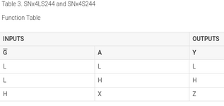
Since this is not what we observe --- A is changing, Y is not --- then we are confronted with another mystery. Either your IC tester is mistaken and U8C is faulty, or there is something wrong with other devices on to \READ: they're somehow able to supply strong enough current to \READ at +5V that despite U8C's best efforts, it can't pull \READ down to 0V when it needs to. (Or there's a problem with the wiring itself, like there wasn't last time.) I'm not certain what would be a likely candidate for a bad IC yet --- there are several ICs on the CPU board that listen to \READ.
Meanwhile: as for pin 19 always remaining low, it looks like the BGACK signal going into pin 19 may not behaving as we might expect. Let's trace it backwards. There are several ICs that listen to BGACK, but in your setup there should only be one device driving it, which is U6A --- a NOR gate that's being used as an inverter. And that NOR gate should only be driven by the CPU at the moment since there are no other cards in the machine.
Measure CPU pin 12. If you see activity there, or if it's also low, then U6A pin 13 is not emitting the value that it should, and this should be investigated further.
Regarding pin U8C: very interesting, but very confusing! If pin 19 is LOW, then U8C should be passing (well, after inversion) READ through it: if you don't believe me, you can check the datasheet
SN74LS244 datasheet | TI.com
SNx4LS24x, SNx4S24x Octal Buffers and Line Drivers With 3-State Outputs
www.ti.com

Since this is not what we observe --- A is changing, Y is not --- then we are confronted with another mystery. Either your IC tester is mistaken and U8C is faulty, or there is something wrong with other devices on to \READ: they're somehow able to supply strong enough current to \READ at +5V that despite U8C's best efforts, it can't pull \READ down to 0V when it needs to. (Or there's a problem with the wiring itself, like there wasn't last time.) I'm not certain what would be a likely candidate for a bad IC yet --- there are several ICs on the CPU board that listen to \READ.
Meanwhile: as for pin 19 always remaining low, it looks like the BGACK signal going into pin 19 may not behaving as we might expect. Let's trace it backwards. There are several ICs that listen to BGACK, but in your setup there should only be one device driving it, which is U6A --- a NOR gate that's being used as an inverter. And that NOR gate should only be driven by the CPU at the moment since there are no other cards in the machine.
Measure CPU pin 12. If you see activity there, or if it's also low, then U6A pin 13 is not emitting the value that it should, and this should be investigated further.
Hi Stepleton,
Thanks for answering on the lats post.
I think U8C is good, because I see the same (pulsing) signal on pin 9 (it is output Y) as on pin 11 (input A from the function table). I also don't believe that IC tester could be wrong for such easy chip.
When I got removed chips on bad board from sockets (ROMs, U8B, U9B) pin 11 on U8C was static HIGH and pin 9 was also HIGH - I wrote about it earlier. On the good board those pins ale pulsing with removed chips from sockets (ROMs, U8B, U9B).
U6A pin 13 has value static LOW.
I am attaching also measurements from CPU pin 18 and U8C pin 11 and pin 9 - situation when all chips are on the board.
CPU pin 18 (CH1) and U8C pin 11(CH2)
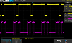
CPU pin 18 (CH1) and U8C pin 9 (CH2)
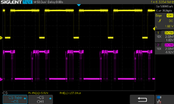
Thanks for answering on the lats post.
I think U8C is good, because I see the same (pulsing) signal on pin 9 (it is output Y) as on pin 11 (input A from the function table). I also don't believe that IC tester could be wrong for such easy chip.
When I got removed chips on bad board from sockets (ROMs, U8B, U9B) pin 11 on U8C was static HIGH and pin 9 was also HIGH - I wrote about it earlier. On the good board those pins ale pulsing with removed chips from sockets (ROMs, U8B, U9B).
With all chips in sockets pin 12 of 68000 CPU has value static HIGHMeasure CPU pin 12. If you see activity there, or if it's also low, then U6A pin 13 is not emitting the value that it should, and this should be investigated further.
U6A pin 13 has value static LOW.
I am attaching also measurements from CPU pin 18 and U8C pin 11 and pin 9 - situation when all chips are on the board.
CPU pin 18 (CH1) and U8C pin 11(CH2)

CPU pin 18 (CH1) and U8C pin 9 (CH2)

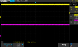
I am attaching measurements from U8C pin 11 and pin 9 - situation when 68000 CPU is in socket, but ROMs, U8B and U9B chips are removed from the good and bad board.
Bad board U8C pin 11 and pin 9 (with CPU inserted and ROMs, U8B, U9B removed):
Good board U8C pin 11 and pin 9 (with CPU inserted and ROMs, U8B, U9B removed):
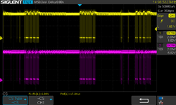
PIN 19 in U8C is LOW in both cases. So in my opinion we should look evidence here, why \READ pin which goes to pin 11 U8C is not pulsing (as it does on a good board) when ROMs U8B and U9B chips are removed .
Is a something else that has impact on CPU code that its pin 9 (and pin 11 on U8C) is always HIGH on bad board? Or is it somenting after U8C? hmm
Bad board U8C pin 11 and pin 9 (with CPU inserted and ROMs, U8B, U9B removed):

Good board U8C pin 11 and pin 9 (with CPU inserted and ROMs, U8B, U9B removed):

PIN 19 in U8C is LOW in both cases. So in my opinion we should look evidence here, why \READ pin which goes to pin 11 U8C is not pulsing (as it does on a good board) when ROMs U8B and U9B chips are removed .
Is a something else that has impact on CPU code that its pin 9 (and pin 11 on U8C) is always HIGH on bad board? Or is it somenting after U8C? hmm
hi Stepleton,
I did further investigation and compared CPU 68000 pin signals on both boards. I have only CPU 68000 connected (no ROMs, U8B and U8B) on both boards.
On the bad board data lines pins D0-D15 has a HIGH +5v signal and look ok. This is probably because we see \READ signal HIGH on pin 9.
Address lines pins A1-A20 has pulsing activity from 0 to +5v and these are also looking ok.
I found four suspected pins values on bad board. Rest pins look fine and similar.
Pin 22 (BERR) on CPU 68000 is pulsing on good board. On bad bird this pin had HIGH signal.
And pins 26-28 looks different, especially Pin 28 on CPU 68000 in bad board doesn't look like good TTL. It goes to U10C. I wonder if this chip isn't failed.
Here are the pictures from pins.
Pin 22 on CPU 68000 in good board:
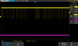
Pin 22 on CPU 68000 in bad board:
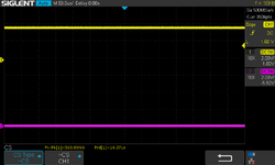
Pins 26-28 on CPU 68000 in good board look different than on bad board:
Pin 26 on CPU 68000 in good board:
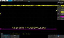
Pin 26 on CPU 68000 in nad board:
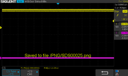
Pin 27 on CPU 68000 in good board:
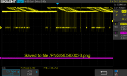
Pin 27 on CPU 68000 in bad board:
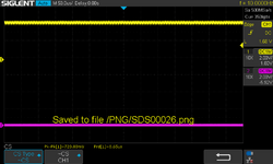
Pin 28 on CPU 68000 in good board:
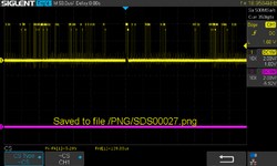
Pin 28 on CPU 68000 in bad board:
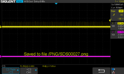
I did further investigation and compared CPU 68000 pin signals on both boards. I have only CPU 68000 connected (no ROMs, U8B and U8B) on both boards.
On the bad board data lines pins D0-D15 has a HIGH +5v signal and look ok. This is probably because we see \READ signal HIGH on pin 9.
Address lines pins A1-A20 has pulsing activity from 0 to +5v and these are also looking ok.
I found four suspected pins values on bad board. Rest pins look fine and similar.
Pin 22 (BERR) on CPU 68000 is pulsing on good board. On bad bird this pin had HIGH signal.
And pins 26-28 looks different, especially Pin 28 on CPU 68000 in bad board doesn't look like good TTL. It goes to U10C. I wonder if this chip isn't failed.
Here are the pictures from pins.
Pin 22 on CPU 68000 in good board:

Pin 22 on CPU 68000 in bad board:

Pins 26-28 on CPU 68000 in good board look different than on bad board:
Pin 26 on CPU 68000 in good board:

Pin 26 on CPU 68000 in nad board:

Pin 27 on CPU 68000 in good board:

Pin 27 on CPU 68000 in bad board:

Pin 28 on CPU 68000 in good board:

Pin 28 on CPU 68000 in bad board:

stepleton
Well-known member
I'm confused again --- I thought we had said that READ was stuck on the bad board. Here's where I got that from:I think U8C is good, because I see the same (pulsing) signal on pin 9 (it is output Y) as on pin 11 (input A from the function table). I also don't believe that IC tester could be wrong for such easy chip.
Is it the case that READ is not stuck anymore? Or you are saying READ is stll stuck on the bad board, but it looks to you like there's a different reason for it than U8C?bad board has strange HIGH static signal +5V.
Pin 1 comes from READ (pin 9) signal from 68000 through U8C chip, so I decided to stop here.
I'm sorry to ask for this, but between two boards and numerous bad chips, I'm starting to lose track of everything! Do you think it might be possible for you to collect two lists:
1. A list of all the chips we've investigated, how we've tested them, and what we believe their status to be? So far we've investigated and tested: the 68000 (by swapping), U8B, U9B, U8C, plus a few others? Collecting all the facts, evidence, and observations about our investigations will be useful.
2. A list of everything we've found so far that's suspicious behavior, or behaviour that's different between the bad board and the good board.
Don't worry about adding oscilloscope trace images --- we can always look earlier in the thread for those.
As for U10C: the "bad TTL" input doesn't look too suspicious to me right now; I suppose I've seen worse. The little spikes could be crosstalk from a nearby signal line. It's an AND gate --- what does the output on pin 8 look like?
Hi stepleton,
I will try to gather this info as we did a lot of investigations before...
But..I got something interesting that can have impact on all.
Except all those previous investigations I managed to get the same status of the behavior on good board as on bad board.
How?: When I was testing pins on U10C on good board with 6800 CPU connected and removed ROMS, U8B and U9B IC's. I observed the same measurements on scope on its pins as on bad board with the same IC's removed and 68000 CPU connected. Meanwhile
I noticed on the CTR screen (with good board connected) a little white dots following in vertical lines (I didn't see those dots before). It was the first time of such behavior I noticed, because when I was testing good board before I got frozen white image with lines on CRT. I have to add here that I do not observerving those white dots on bad board connected.
So I disconnected power cord from power supply and connected again, turned on Lisa (with the same good board) and I got frozen white image with white lines on CRT. Then I did measurements on the pins on U10C. They looked normal.
When I compared it to U10C pins measurements from good board (with failed status I described above) and bad board U10C pins measurements they were looking the same!
This turns me to the thought that it may be something wrong with current supply of bad board or there is one chip that fails to give enough current.
I don't know if this information is valuable for you, but I decided to write you about it.
I am getting regular the same behavior on good board now (with white dots), when I am turning on LISA. I have to reset power supply and frozen white picture comes back on CRT.
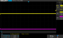
I am attaching the pins values that were different on U10C during measurement on bad board and below good board (with good status on CRT). They are only pins 9,10,11 Pin 8 has always on both board value LOW.
Pins 8,9,10,11 U10C on bad board:
Pin 8:
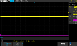
Pin9:
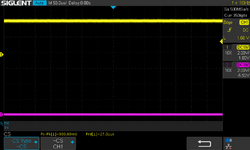
Pin10:
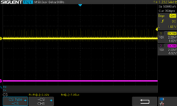
Pin11:
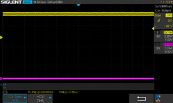
Pins 8,9,10,11 U10C on good board (with good status after PSU restart):
Pin 8:
Pin 9:
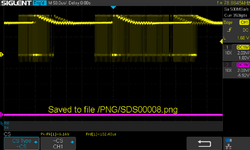
Pin 10:
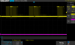
Pin 11:
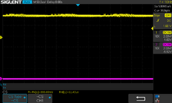
I will try to gather this info as we did a lot of investigations before...
But..I got something interesting that can have impact on all.
Except all those previous investigations I managed to get the same status of the behavior on good board as on bad board.
How?: When I was testing pins on U10C on good board with 6800 CPU connected and removed ROMS, U8B and U9B IC's. I observed the same measurements on scope on its pins as on bad board with the same IC's removed and 68000 CPU connected. Meanwhile
I noticed on the CTR screen (with good board connected) a little white dots following in vertical lines (I didn't see those dots before). It was the first time of such behavior I noticed, because when I was testing good board before I got frozen white image with lines on CRT. I have to add here that I do not observerving those white dots on bad board connected.
So I disconnected power cord from power supply and connected again, turned on Lisa (with the same good board) and I got frozen white image with white lines on CRT. Then I did measurements on the pins on U10C. They looked normal.
When I compared it to U10C pins measurements from good board (with failed status I described above) and bad board U10C pins measurements they were looking the same!
This turns me to the thought that it may be something wrong with current supply of bad board or there is one chip that fails to give enough current.
I don't know if this information is valuable for you, but I decided to write you about it.
I am getting regular the same behavior on good board now (with white dots), when I am turning on LISA. I have to reset power supply and frozen white picture comes back on CRT.
I am attaching the pins values that were different on U10C during measurement on bad board and below good board (with good status on CRT). They are only pins 9,10,11 Pin 8 has always on both board value LOW.
Pins 8,9,10,11 U10C on bad board:
Pin 8:

Pin9:

Pin10:

Pin11:

Pins 8,9,10,11 U10C on good board (with good status after PSU restart):
Pin 8:

Pin 9:

Pin 10:

Pin 11:

Similar threads
- Replies
- 13
- Views
- 953
- Replies
- 3
- Views
- 1K
- Replies
- 3
- Views
- 497

