• Updated 2023-07-12: Hello, Guest! Welcome back, and be sure to check out this follow-up post about our outage a week or so ago.

Problem with Apple Lisa 2 CPU Board - not booting

Greniu

Active member
Hello Colleagues.
I found this interesting simmilar thread (here ) and I have the same problem as BEU, but unfortunately I don't get error 41.
I still have the same symptom of flickering black and white squares on the CRT with only the CPU board inserted like BEU had on the beginning of his thread. I know that CPU board is bad, because I have a second working Lisa and there is the same symptom when I swap the CPU board.

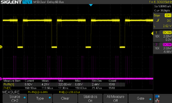
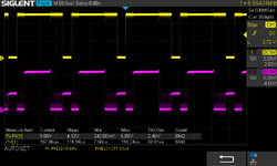
From an interesting study of the pin values analysis with an oscilloscope, I discovered that pin 41 on the CPU (UA13) has a value of 1.82V but there is activity on it. There is also 1.82V on pin 2 of both ROMs and the activity. Also pin 44 of the CPU (UA16) has 1.82V and activity is observed on it on the oscilloscope.

I have the same behavior on RESET pin 18 on CPU as BEU (it is not static HIGH) , Pin 15 clock is perfect. I have checked these values on a working CPU board and they are different.

Interesting find is that CPU RESET pin (18) has the same shape of wave and value as SRAMs 7 pin - there is no activity on that pin.

I have also checked 3 SRAMs - I swapped them to a working CPU board. I also changed the processor - everything is here and working.
I have checked continuity on SRAM pins and the 3 sockets pins by multimeter when chips are inserted - they seem to be ok. I have not resoldered the sockets of SRAM chips. Do you think I should do it?

I have IC tester and checked ICs: 7417 (U2E), 74F283 (U8A, U9A, U10A), 74lS1002 (U5B), 74LS245 (U11A), 74LS245 (U11B), 74LS245 (U15E), 74LS138(U13F), 74LS139 (U14F) and they are ok
CPU, both ROMS, VSROM, SRAMs are ok. I tested them on working Lisa.

I will be grateful for any help and tips.
 

stepleton

Well-known member
Thanks for starting the new thread. Thanks to your swapping components, it looks like we know a lot already, which is a good start. It's nice that the problem is known to be localised to the CPU board.

If I understand correctly, \RESET is behaving strangely, so let's begin there. Can you share an image of the oscilloscope trace for \RESET?

Does this \RESET behaviour look the same if only the CPU board and no other boards are plugged in?

Let's consider these schematics:

(By the way: I think these GIFs were handmade copies drafted by someone with access to the official Apple schematics. We do have the official Apple schematics here on Bitsavers --- actually two versions for two different CPU board revisions --- but I find the GIFs easier to deal with than the PDFs. Just know that if something on the GIF schematics doesn't seem to match what you find on your CPU board, it's good to check the official schematics on Bitsavers in case the GIF artist made a mistake or in case you have a different board revision.)

Looking at sheet 3, we find that the IC closest to \RESET line is U2E, a 7417 open-collector hex buffer. You say you've tested it, but what does it look like in-circuit? Can you share or describe 'scope measurements on U2E pins 1, 2, 3, and 4?

One last note about chip testers: while I think that they are very trustworthy when they tell you that a chip is bad, they are not as accurate when they say that an IC is good. Usually the testers test an IC at signal frequencies that can be different (potentially lower) than what the IC encounters in-circuit, and they also don't put the same load on IC outputs that the IC might find in the real world. A marginal or failing IC can have enough capability remaining to satisfy a chip tester, but still fail when put to use in the "real world". What kind of chip tester do you use?
 

Greniu

Active member
Hi Stepleton,

Thank you for quick reply and advices.
Regarding your questions:
1. I am pasting of an image of \RESET pin 18 on CPU after Reset button push on Lisa motherboard.
Pin 18 is CH1
SDS00001.png
2. Yes, \RESET behaviour look the same if only the CPU board and no other boards are plugged in. The. same measurement I have on pin 7 on the expansion slot in both cases (with I/O board plugged in and without).
3. I got those schematics in *.tif format with good quality and they are for 050-4009-H revision (the same as my CPU board). So I am using it to check what might be wrong.
4. I have swapped 7417 (U2E) from working CPU board and the behavior is the same. I am using also TSH‑06F IC tester to test chips that may fail. This tester also recognize 7417 and test it with success.
5. I am attaching below measurements from pin 1,2,3,and 4 from my scope (after Reset button pushed) on 7417. I have also compared it from the working CPU board and they all have static HIGH line.

PIN 18 on CPU (CH1) and PIN 1 (CH2) on 7417 (after RESET button pushed)
SDS00001.png

PIN 18 on CPU (CH1) and PIN 2 (CH2) on 7417 (after RESET button pushed)
SDS00002.png

PIN 18 on CPU (CH1) and PIN 3 (CH2) on 7417 (after RESET button pushed)
SDS00003.png

PIN 18 on CPU (CH1) and PIN 4 (CH2) on 7417 (after RESET button pushed)

SDS00004.png

Measurements on a working CPU board have all static +5V line on PIN 18 on CPU and on 1,2,3,4 pins on 7417 IC


Thanks.
 

Greniu

Active member
Can CPU trigger reset signal by himselves because something else is wrong (error)? Assuming 7417 is ok and from the schematics and measurements it looks that CPU trigger reset signal.Zrzut ekranu 2023-05-27 o 15.53.52.png
 

stepleton

Well-known member
Thanks for answering all the questions and sharing trace images so quickly.

OK, all those signals look just fine, so it's probably the CPU that's resetting itself for the reasons that were discussed in the previous thread. (The CPU can assert \RESET whenever it executes a \RESET instruction.) I think I'd misread and thought that \RESET was operating at levels that aren't TTL.

When I have more time later, I'll try to think about the signal lines that you said were behaving in an unusual way --- plus, I seem to recall that the CPU can toggle \RESET in a pattern that provides some hint as to what's going wrong.. In the meantime, can you share 'scope images for the signals that were behaving strangely --- UA13 and UA16 coming out of the CPU, as well as the ROM pins you mentioned.

Do I understand correctly that pin 2 of both ROMs is acting strangely? This is a bit unexpected to me, as they both connect to different data lines. Either way, could we get images of traces there, too?

Thanks again!
 

Greniu

Active member
Thanks. I am pasting schematics and pins measurements.
Zrzut ekranu 2023-05-27 o 18.27.23.png

I am pasting images from scope Pins from ROM and from CPU:

RESET PIN 18 on CPU (CH1) and PIN 2 UA13 (CH2) on 341-0175 and PIN 2 (CH2) 341-0175 ROM:
SDS00005.png

RESET PIN 18 on CPU (CH1) and PIN 43 UA15 (CH2) on CPU:


RESET PIN 18 on CPU (CH1) and PIN 37 UA09 (CH2) on CPU:
SDS00001.png

RESET PIN 18 on CPU (CH1) and PIN 38 UA10 (CH2) on CPU:
SDS00002.png

RESET PIN 18 on CPU (CH1) and PIN 39 UA11 (CH2) on CPU:
SDS00003.png

RESET PIN 18 on CPU (CH1) and PIN 40 UA12 (CH2) on CPU:
SDS00004.png

RESET PIN 18 on CPU (CH1) and PIN 41 UA13 (CH2) on CPU:
SDS00005.png

RESET PIN 18 on CPU (CH1) and PIN 42 UA14 (CH2) on CPU:
SDS00006.png
RESET PIN 18 on CPU (CH1) and PIN 43 UA15 (CH2) on CPU:
SDS00007.png
RESET PIN 18 on CPU (CH1) and PIN 44 UA16 (CH2) on CPU:
SDS00008.png
RESET PIN 18 on CPU (CH1) and PIN 45 UA17 (CH2) on CPU:
SDS00009.png
RESET PIN 18 on CPU (CH1) and PIN 46 UA18 (CH2) on CPU:
SDS00010.png
RESET PIN 18 on CPU (CH1) and PIN 47 UA19 (CH2) on CPU:
SDS00011.png
RESET PIN 18 on CPU (CH1) and PIN 48 UA20 (CH2) on CPU:
SDS00012.png
RESET PIN 18 on CPU (CH1) and PIN 50 UA21 (CH2) on CPU:
SDS00013.png
RESET PIN 18 on CPU (CH1) and PIN 51 U22 (CH2) on CPU:
SDS00014.png
RESET PIN 18 on CPU (CH1) and PIN 52 UA23 (CH2) on CPU:
SDS00015.png
 

Attachments

  • SDS00006.png
    SDS00006.png
    34.5 KB · Views: 1

Greniu

Active member
I have one interesting find. I removed both ROMs from working and non working CPU board. I compared CPU signals on pins of both CPU boards when power on. They look simmillar. So I thought it must be something with ROM sockets? (ROM chips are tested and working fine.
I have measured with multimeter resistance between pin 14 and pin 28 of both ROMs sockets. The working board shows 380 ohm, and non working board 96 ohms. So maybe here is the problem?
 

stepleton

Well-known member
Thanks for these traces. And apologies for what I said about pin 2 on both ROMs earlier --- I said they corresponded to different data bits, but I was thinking of the O2 output, not pin 2, which corresponds to UA13 for both ICs.

Based on your traces, it looks like address lines 9-16 are behaving oddly. Lines 17-23 look like good TTL signals. We don't have measurements for address lines 1-8.

Perhaps not coincidentally, address lines 9-16 all feed into 74F283 adders on sheet 4 of the schematic, ICs U8B and U9B. This will be part of the Lisa's MMU. Your post at the beginning of the thread suggests that you haven't tested U8B and U9B, but it does say that you tested 74F283 ICs, and at a glance I don't think there are other 283s on the CPU board. Perhaps you did test these ICs after all?

It seems that U8B and U9B might deserve more attention. Can you say whether you've tested these in your chip tester? Can you do some probing around the inputs and outputs to these ICs to see if you find more suspicious voltages?

-----

I don't think the measurement of the resistance between Vcc and ground for the ROMs can tell us very much just yet. These power rails are shared by nearly all of the ICs on the CPU board, and so (a) if they indicate a problem, the problem could be with virtually any IC (or even other components like bypass capacitors), and (b) even the same ICs made by different manufacturers could vary in the resistances you can measure here. Of course, if you measured very high or very low resistances, it would be a different story.

That said, it's a good reminder that broken ICs can sometimes reveal themselves by consuming unexpected amounts of power. Do you have a thermal camera? Can you take a thermal picture of your CPU boards during (seems unlikely) or immediately after running them in your Lisa for a while? Chips that are malfunctioning might be hotter or (rarely) cooler than they should be. If you don't have a thermal camera: are any of the chips getting unusually hot?
 

Greniu

Active member
Thank you stepleton.
Yes I tested 3 x 74F283 (U8B,U9B,U10B) only on IC tester. Do you think they may be faulty?

I am attaching below measurements from A1(UA1) - A8 (UA8) on CPU.
RESET PIN 18 on CPU (CH1) and PIN 29 UA1 (CH2) on CPU:
SDS00001.png

RESET PIN 18 on CPU (CH1) and PIN 30 UA2 (CH2) on CPU:
SDS00002.png

RESET PIN 18 on CPU (CH1) and PIN 31 UA3 (CH2) on CPU:
SDS00003.png
RESET PIN 18 on CPU (CH1) and PIN32 UA4 (CH2) on CPU:
SDS00004.png
RESET PIN 18 on CPU (CH1) and PIN 33 UA5 (CH2) on CPU:
SDS00005.png
RESET PIN 18 on CPU (CH1) and PIN 34 UA6 (CH2) on CPU:

SDS00007.png

RESET PIN 18 on CPU (CH1) and PIN 35 UA7 (CH2) on CPU:
SDS00007.png
RESET PIN 18 on CPU (CH1) and PIN 36 UA8 (CH2) on CPU:
SDS00008.png
 

stepleton

Well-known member
Thanks for these additional traces. A1-A8 don't look nearly as suspicious to me as A9-A16 do. I'm a little curious about the intermediate voltage level during the \RESET assertion, but given that the computer doesn't do anything while \RESET is asserted, I don't think this is a very important factor right now; it could mean that the 68000 is simply not driving the address bus. (I don't know if the 68K goes high-impedance on the address bus during reset, but it would be a reasonable thing to do, and the 68000 data sheet does say that the address bus is a tri-state bus.) Maybe it's a clue for later.

The fact that all of A9-A16 behave strangely is a little difficult to explain in an easy way. If we only saw A9-A12 or A13-A16 behave strangely, we could be more certain that one of the chips was bad. Having two chips fail in the same way at the same time is more unusual, and it leads me to wonder if there's something we're missing. We may need to keep thinking about this some more :)

Can you do a good check of all of the other pins of U8B and U9B besides the address bus inputs? That's all the pins besides 2, 6, 11, and 15. It's not necessary to share images of these measurements if they look like good TTL signals (i.e. 0V and +5V levels only, with rapid rise and fall times --- no gradual slopes; you may want to use a shorter timebase to verify that the level transitions are fast). If you do see something that doesn't look like TTL, that would be good to know.

Have you investigated the 68000's \HALT pin (pin 17)? I believe it should be remaining high except right after power-up or right after you press the Lisa's RESET button. If it's pulsing like \RESET is, then that's something else to investigate.
 

Greniu

Active member
I am sharing some images forom U8B pins:

PIN 1 U8B:
PIN 1 U8B .png

PIN 2 U8B:
PIN 2 U8B - UA10.png
PIN 3 U8B:
PIN 3 U8B.png
PIN 4 U8B:
PIN 4 U8B.png
PIN 5 U8B:
PIN 5 U8B.png
PIN 6 U8B:
PIN 6 U8B - UA9.png
PIN 7 U8B:
PIN 7 U8B.png
PIN 8 U8B:
PIN 9 U8B.png
PIN 9 U8B:
PIN 9 U8B.png
PIN10 U8B:
PIN 10 U8B.png
PIN 11 U8B:
PIN 11 U8B -UA12.png
PIN 12 U8B:

PIN 12 U8B.png

PIN 13 U8B:
PIN 13 U8B.png

PIN 14 U8B:
PIN 14 U8B.png

PIN 15 U8B:
PIN 15 U8B - UA11.png

PIN 16 U8B:

PIN 16 U8B.png
 

Attachments

  • PIN 7 U8B.png
    PIN 7 U8B.png
    31.2 KB · Views: 1

Greniu

Active member
Hi Stepleton, Thank for reply.
Regarding \HALT pin on CPU it is static HIGH, no pulses.
I am sharing also images from U9B of all pins. Yellow pin is CPU RESET pin:

PIN 1 U9B:
PIN 1 U9B.png
PIN 2 U9B:
PIN 2 U9B - UA14.png
PIN 3 U9B:
PIN 3 U9Bpng.png
PIN 4 U9B:
PIN 4 U9B.png
PIN 5 U9B:
PIN 5 U9B.png
PIN 6 U9B:
PIN 6 U9B - UA13.png
PIN 7 U9B:
PIN 7 U9B.png
PIN 8 U9B:
PIN 8 U9B.png
PIN 9 U9B:
PIN 9 U9B.png
PIN 10 U9B:

PIN 10 U9B.png

PIN 11 U9B:
PIN 11 U9B - UA16.png
PIN 12 U9B:
PIN 12 U8B.png
PIN 13 U9B:
PIN 13 U9B.png
PIN 14 U9B:
PIN 14 U9B.png
PIN 15 U9B:
PIN 15 U9B - UA15.png
PIN 16 U9B:
PIN 16 U9B.png
 

Greniu

Active member
I am still wondering what might be the cause of those LOW pulses on CPU \RESET pin occurring regularly (yellow CH1 on scope). Those pulses are seen on U8B, U9B IC's and almost on every measurement I sent on CH2. I don't think U8B and U9B are bad. I checked them on IC tester and based on the images we can see that they are processing instructions but then brake after PCU \RESET goes LOW. I may desolder them and swap with working CPU board ones, but based on the pictures I think that sum functions is correct on them.

I think those LOW pulses cause brake in processing instructions and CPU regularly restarts.
When faulty board in powered on I can feel VSROM very hot, 3 SRAMs and CPU are hot. Is it because all the processing is in loop mode because of CPU restarts? Something is causing CPU \RESET pin to go LOW repeatly when it is connected to socket.

Interesting situation and problem. Thank you for any help. I appreciate it. Maybe by this problem we will know about CPU board and debugging.
 

stepleton

Well-known member
Thanks for sharing more measurements of U8B and U9B. None of the other pins look mysterious to me right now.

Since you've verified that \HALT is remaining high, we can be virtually certain that the CPU \RESET pulses are coming from the CPU executing RESET instructions from the boot ROM, probably from the MMUERR routine and nearby code. The fact that there is one repeating \RESET pulse and not two (as we saw in the other thread) suggests that the "R/W error" condition mentioned in the ROM source code is what's responsible. Note that problems with U8B and U9B, as well as the SRAMs or other parts of the MMU, are exactly the kind of thing that can cause the CPU to detect an error and execute MMUERR.

We could verify this theory by measuring what address the CPU is executing --- do you have a logic analyser?

U8B and U9B may not be bad, but something is pulling down the bus so that address signals UA9-UA16 can't reach +5V. Even if this isn't the cause of the problem that gives your Lisa trouble with booting, I think we should try to understand what's going on here. There's a chance that the 68000 is passing a lot of current into those address bus lines in its attempt to raise their voltages to +5V, and this probably isn't healthy for the CPU.

The mystery is that there aren't too many chips that listen to UA9-UA16, especially when there are no other cards in the computer. From my reading of the schematics, there's the boot ROM ICs and U8B+U9B, and nothing else.

You mention that you've tested U8B and U9B in an IC tester. Does this mean that you have these ICs in sockets on your CPU board?

If so, can we see what happens to some of the address lines in UA9-UA16 with U8B and U9B removed from the CPU board? It would be interesting to find out whether the address bus signals still showed non-TTL values.
 

stepleton

Well-known member
PS: It doesn't sound too surprising to me that the CPU and the various memory devices you've identified get hot. Can you compare the warmth you're feeling with the same ICs on your working CPU board?
 

Greniu

Active member
PS: It doesn't sound too surprising to me that the CPU and the various memory devices you've identified get hot. Can you compare the warmth you're feeling with the same ICs on your working CPU board?
Hi Stepleton,
Thanks for interesting information.Your knowledge is amazing. I will check those U8B and U9B ICs - desolder. They are soldered. to the board, so I can desolder them again from board and swap with the other ones from workin board. I will also measure pins on the socket when they are pulled out.
I don't have logic analyzer unfortunately:(
But before I delsolder them, looking on the schematics maybe we have some problems with U5B or U6D? From U5B there is a PIN number 10 which has LOW value in non-working board and has activity in working board. This pin goet to pin 7 on U8B (C0).Then 9pin (C4) from U8B goes to pin 7 on U9B (C0).

About warmth of the chips I wroteealier: I don't feel warmth of those chips on the working board. So the reset activity on CPU causes this IC's to hard continuously work. Maybe that's wy they are getting hot?
 

stepleton

Well-known member
It was good to have observed U5B is another chip we have to consider --- I see that it has UA14 as one of its inputs. Additionally, I just noticed that U14F receives UA15 and UA16 as inputs too.

If necessary, we can try to understand more about what these chips are doing by referring to the Lisa Hardware Manual at https://lisa.sunder.net/LisaHardwareManual1983.pdf . PDF pages 35-45 describes how the MMU works on a software level, and PDF pages 123-132 describes how it works electronically. As you can see from PDF page 41, address bits 14, 15, and 16 have special meanings. There's no doubt that the U5B and U14F are involved in the mechanisms that these bits control.

These chips or others could be malfunctioning, and it would be good to know if they were. We may be returning to those chips later on in our journey. But we still have the strange situation where all of the address lines UA9-UA16 are behaving anomalously, not just UA14-UA16. And only U8B and U9B are touching those address lines specifically.

You're wise to want to try less intensive options before desoldering components from the CPU board. With that in mind, you may wish to try a few other things first:

1. Take another really, really good look at the condition of your CPU board. Is there anything at all that you see that could interfere with the correct operation of the UA9-UA16 address lines? Any trace of flux residue or any other suspicious physical defects? I don't think it's likely that you'll discover a problem, but it's always worth having another look.

2. If you haven't done it already, consider swapping the 68000 from the good CPU board into the bad board, then repeating the UA9-UA16 measurements. If you find that all of those signals now reach +5V, then we can be reasonably certain about two things: (1) the 68000 from your bad board has damaged drivers on UA9-UA16, and (2) assuming your CPU board doesn't work even with the new 68000, then there are more problems to solve.

If the 68000 swap shows no difference in UA9-UA16, then I think removing these ICs may be a sensible next step. Do you have good tools for desoldering through-hole components? If you do, it can be more reasonable to consider removing other ICs in the future.
 

Greniu

Active member
hi stepleton,

I removed U8B and U9B (desoldered them) and measured UA9-UA16 pins on the sockets. I think that 74F283's are ok (but I will be 100% sure if I swap them with ones from good board). But please see below screens from scope and please let me know what you think.
Meanwhile I desoldered U5B, U6D and U14F and checked them on IC tester and tests went ok.
CPU Swap makes no difference. The sedond good board boot on the bad board CPU.
So the situation became interesting.

Screens with values when UA8 and UA9 are removed:
RESET PIN 18 on CPU (CH1) and PIN 6 UA9 (CH2) on U8B:
SDS00002.png

RESET PIN 18 on CPU (CH1) and PIN 2 UA10 (CH2) on U8B:
SDS00003.png

RESET PIN 18 on CPU (CH1) and PIN 15 UA11 (CH2) on U8B:
SDS00004.png

RESET PIN 18 on CPU (CH1) and PIN 11 UA12 (CH2) on U8B:
SDS00005.png


RESET PIN 18 on CPU (CH1) and PIN 6 UA13 (CH2) on U9B:
SDS00006.png
RESET PIN 18 on CPU (CH1) and PIN 2 UA14 (CH2) on U9B:
SDS00007.png

RESET PIN 18 on CPU (CH1) and PIN 15 UA15 (CH2) on U9B:
SDS00008.png

RESET PIN 18 on CPU (CH1) and PIN 11 UA16 (CH2) on U9B:
SDS00009.png
 

Greniu

Active member
Apologize for an error in previous post. Of course screens with values when U8B and U9B are removed (UA8 and UA9).
 

stepleton

Well-known member
Thanks for this. These signals look a lot more like TTL, except for UA12, which is still not able to rise above +5V for reasons I don't understand. The only thing that is receiving UA12 at this point is the boot ROM.

From what you've written: when you installed the 68000 from the good CPU board into the bad CPU board, it sounds like the bad CPU board was still not working.

Did you inspect any of the signals UA9-UA16 on the bad CPU board when the good CPU board 68000 was installed there? If you did, did the signals look as suspicious as the ones we saw when the U8B and U9B were installed?

I am trying to eliminate the possibility that your bad CPU board 68000 has weak address line drivers for lines UA9-UA16.
 
Top