• Updated 2023-07-12: Hello, Guest! Welcome back, and be sure to check out this follow-up post about our outage a week or so ago.

PDS Angle Adapter

tt

Well-known member
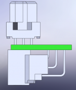
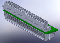
Here is another brainstorm topic if anyone has some comments into technical issues with this idea. I am trying to see if I can adapt the PDS pass-through slot on the Asante MacCon SE/30 / IIsi card that has the PDS slot going the wrong direction for the SE/30. Gamba outlined the issues here: http://home.earthlink.net/~gamba2/se30_pds_multiple.html#3cgs The solution relies on using a right angle euroDIN connector, but in a way not really intended by the connector and not very mechanically secure. I tried some effort in desoldering the connector, but I got frustrated with it, I may try again. But in the meantime I thought of making this:
PDS angle adapter.png

I quickly put this mock-up together with models conveniently provided by Tyco Electronics. It will pretty much put the card in-line with where it should be without requiring mods and be more mechanically secure. The unfortunate thing is this board will have to be 4-layers unless there is something I am overlooking, so it will be more expensive to make. From an electrical perspective, does anyone see any issues? Should I have a ground plane somewhere to make use of the extra 4th layer, and should it be in the middle?


Trash80toHP_Mini

NIGHT STALKER
The thru-hole legs of both sockets are interfering with the shroud of the other on that board as pictured, so there appears to be no room to get at the soldertails to make the connections. If you make enough room for such separation, will there be scootch side to side in the SE/30 to fit the assembly?

IMHO it's overly complex, unless you're dead set upon keeping your PDS card stock.

The approach bbraun and I have independently developed is to de-solder the right angled (straight connector) passthru connector and replace it with a "left-angle" female socket pointing straight up. We've jokingly called this the WrongAnglePDS connector hack in PM.

I'd suggest doing something more along the lines of a cut down version of that exceedingly expensive Japanese board, forgoing the IIci Cache Slot PAL adaptation. Concentrate upon getting more standard Slots onto the SE/30 PDS in the alloted cubic. I think that's eminently doable and in no way a copy of the other card.

That said: the simple way . . .

knuckledraggerdoom2p.jpg.bdff5e9bd9f811ca25ae129e9cb1cae5.jpg
The process is ugly, but the results are elegant and it works!

iisiradiuscpiiflatsuper.jpg.d696c60ba54b3572995a8fa8c9ede13a.jpg
I've got three of the Asante NICs to test before starting on one. }:)


tt

Well-known member
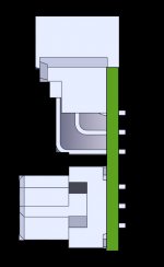
The thru-hole legs of both sockets are interfering with the shroud of the other on that board as pictured, so there appears to be no room to get at the soldertails to make the connections.
It's an optical illusion, there is room for both sockets. The only tricky thing is the straight-through connector on top needs to be soldered so the tails are about flush on the underside of the board.

PDS angle adapter side view.png

IMHO it's overly complex, unless you're dead set upon keeping your PDS card stock.
Not really, I just wasn't successful at removing the connector in the past. The conector on the Asante board is close to components, so it seems like they would be in the way to hack at it like that.


Trash80toHP_Mini

NIGHT STALKER
I see what you're getting at now, not bad at all* though I'm not sure how well soldering would go without the soldertals extending to make contact with the tip.

One fly in the mud . . .

. . . even cutting the PCB back to the bare minimum so as to just barely allow room for the outboard row of pins for your RA Male connector, you're talking about .95" of assembly width and more like 1.05" from the surface of the adapted card as shown.

Try swapping the connector configurations, put a straight up Male Connector on a Verticallly oriented PCB, with the Right (Left?) Angle Female Connector mounted to that vertical PCB. It's late and you've just made me cross-eyed, but I think that'll get your lateral clearance requirement down to something on the order of .75" and dispense with the need to have your soldertails buried down into the PCB by increasing the vertical offset a bit.

Let me know if that crosses your eyes up as well. :lol:

* obligatory Independence Day reference. [:eek:)] ]'>


tt

Well-known member
. . . even cutting the PCB back to the bare minimum so as to just barely allow room for the outboard row of pins for your RA Male connector, you're talking about .95" of assembly width and more like 1.05" from the surface of the adapted card as shown.
Yeah, the HD cage is going to be in the way.

Try swapping the connector configurations, put a straight up Male Connector on a Verticallly oriented PCB, with the Right (Left?) Angle Female Connector mounted to that vertical PCB.
Makes sense. I don't think there's a left version, so the keying will be off if I'm looking at it right.

Well, I think you've convinced me to try removing the connector again on the Asante NIC. Would you be able to describe the steps, such as desolder then bite into the connector, or desolder after? How far down do you have to bite down, can you get away with going down half way?

I was also thinking about cutting into it with Dremel cutting wheel and chopping it down to ~1/3 the height. The approach here is to try to free up the pins so they can be removed individually without being incased in the connector's plastic housing.


Trash80toHP_Mini

NIGHT STALKER
I hope you don't mind my butting in . . . can't help it.

Have someone else describe how to do it with chip-quick, that and a heat gun might get it off 1-2-3 . . . dunno . . .

I'd desoldered every connection with a piston type Desoldering Iron. The connector just wouldn't budge overall, too many pins were still hanging up.

I started munching at it from the ends with the jaws of the nippers parallel to the pins, no upward pressure to speak of, just crushed the plastic housing with pressure from the sides. The pins were in shear, pulling them sideways for the most part, not under tension, pulling them straight up from the board wold have likely proved problematic at the PCB level.

Several pins stubbornly refused to let go, so I desoldered each individually after I was finished munching the connector to smithereens.

No damage to the board at all, no matter how scary that first picture looks.

The less connectors involved the better, I think it's capacitance that's the problem when too many connections are involved. One of the electron pushers needs to chime in here, IIRC, I read about it in PC Magazine MANY moons ago.


tt

Well-known member
I hope you don't mind my butting in . . . can't help it.
Not at all, that's why I posted here. :b&w:

Did your nippers have a full byte (toward the PCB base) or half a byte?


tt

Well-known member
It's getting closer! I used a Dremel with a cutting wheel attachment and side cutters to cut off remaining pieces. There was a bunch of chip-quick that got into the connector that made a molten mess as I cut into it, so there's still a little bit of cleaning left to do. I don't think anything got damaged though.

DSC05891.jpg


Trash80toHP_Mini

NIGHT STALKER
That's lookin' really good, tt. Best of luck with the rest of the conversion.

I'm cheating, I'm converting one of the Radius Color Pivot II/IIsi Boards for now. :eek:)


tt

Well-known member
Getting even closer:

IMG_0001_5-crop.jpg

Pins clear with an incorrectly gendered EuroDIN connector I happen to have and the card still works!! So I am ready to solder a connector once I have one. :D


uniserver

Well-known member
hey i have one of these in my IIsi, if i threw this in my se/30 would i have to change the jumper on it to something else?


Trash80toHP_Mini

NIGHT STALKER
Congratulations, tt! [:)] ]'> Check with trag for the wrong-angle connectors.

@ uniserver: The card is designed to work in the SE/30, going from SE/30 can sometimes be problematic. A few of the SE/30 16MHz bus cards have a problem with the IIsi's faster bus. Changing the Slot (interrupt) address is no biggie and AFAIK, there's no possibility of mucking up either machine with an incorrect setting, it just won't see the card on startup.

Run SlotInfo from the Gauge series to find out which Address your card is set to before removing it.Check the docs for the SE/30 to make sure the setting is compatible, if so, just transfer the card. Still working on my first cup of coffee, so it's more than a bit murky between the ears, ATM. ISTR an available address settings shift between the two machines.

If you don't already have them, snag the Developer Notes and Service Manuals for every Mac you have or intend to collect. The former will have more than you'll ever need to know about addressing and the latter speaks for itself. The SE/30 might not be available in .PDF, It's covered in GttMFH2e.


uniserver

Well-known member
wow lookin good!

that is as custom as it gets.

so now you can have a nic card and a video card! :)

all at the same time.


tt

Well-known member
wow lookin good!
that is as custom as it gets.

so now you can have a nic card and a video card! :)

all at the same time.
Thanks, that's the idea. Last night I experimented with a Radius Pivot card. Too bad the IIsi Radis card is not compatible, since it is fairly short and has a pass-through as well. With some card combinations, it might be possible to have three cards stacked up, say if you had a Diimo and some other short card along with the Asante. I am sort of hoping my power supplies run steady with the extra loads. I have been thinking about the insides of the Stratos/Artmix power supply, but it is out of my budget at the moment, and I haven't heard much about it in general.


Trash80toHP_Mini

NIGHT STALKER
I only ever recall the RCPII/IIsi Card being tested once in an SE/30. It didn't work at first using just the Monitors Control Panel as a test indicator. Unfortunately, it was sent back to me before I had a chance to suggest additional testing procedures, I hadn't thought it through fully before sending it along..

I know length fit as the bottom card is an issue in regards the frame. But on top of your very nicely hacked NIC, it just might fit.

I think it was MK558 that tried it, but I'm not sure, it's late and I'm sleepy. Has anyone else tested the card in an SE/30? Gotta find that pos . . . maybe tomorrow.!

Some rigorous testing is needed to definitively rule it out as far as I'm concerned.

 
Top