• Updated 2023-07-12: Hello, Guest! Welcome back, and be sure to check out this follow-up post about our outage a week or so ago.

Modern PSU for the SE/30

superjer2000

Well-known member
I connected my Seasonic PSU to a single spinning platter HDD for 1 hour and the HDD was spinning for that entire 1 hour.  The PSU fan never came on, and it was just as hot to the touch after 1 hour as my previous no-Load test.  Again, I am not surprised the fan did not turn on because the Seasonic makes it clear that it won't turn on if the Load is 30% or less of its output capacity.  Again, this seems to prove there is no temperature sensor or temperature activated fan control in the Seasonic PSU.

UPDATE: Hmmm.  Maybe it does have a temperature sensor after all.  It's pretty hot here in Japan, so I decided to switch off the A/C for a while and then watch the fan.  Sure enough, the fan started spinning.  It spins 8 seconds ON, then 8 seconds OFF, and then that cycle repeats.  The PSU is still quite warm to the touch, even with only that HDD spinning, but at least I now know the fan is working and it seems to be temperature controlled.
Do you have a way to measure the temperature of the Seasonic case?  With the case off,  mine had hot points around key areas of the supply that I didn't consider to be too hot. Seasonic may be targeting uses where there is a preference to not have the fan running (ie home theatre) It would be possible to rewire  it so the fan is always on if that is a priority. 

I can hear the fan in my Seasonic in my SE/30 turn on after around 20 minutes and my SE/30 runs quite cool on its stock fan as measured by my hand on the side of the case and at the fan outlet at the back. 

When i I am home in a week I can set up one of my new units (before disassembly) with a hard disk attached and let you know how warm it gets. 


JDW

Well-known member
No, I don't have a reliable means to measure temperature of my Seasonic.  I can only convey how hot it is to the touch.  In all my use cases to date, I have placed the Seasonic as shown in my photo, with the vent side facing strait up, and I put my hand on that side to determine how hot it gets.

When you check your Seasonic's fan, check to see if it cycles ON for 8 seconds then OFF for 8 seconds like mine does.

I should also mention that when my Seasonic's fan comes on, it's so quiet I cannot hear it when my ear is about 50cm away.  My room is not dead silent, so perhaps that masks the sound.  But normally if a fan is loud I can hear it above ambient room noise.  So while my testing has confirmed the fan does come on, I have not determined if it varies its rotational speed and therefore the noise level.


superjer2000

Well-known member
@JDW  I connected one of my new Seasonics to 3 hard disks and fired it up (before disassembly). After ~3 hours PSU case temp remained static at around 36c at the hottest points.  (Our house is about 22c).  PSU case was warm but definitely not hot and well within what I would call a reasonable temp range. 

The fan fan didn't turn on right away but spun up after probably 15 minutes. It wasn't spinning very fast- I'm not sure if it's variable speed or if that's the only speed. There must be a temp sensor as when I turned off the supply and turned it on again the fan spun sooner than from cold. 

I hope your your supply isn't damaged. I ended up ordering four more when I was in the US on vacation last week as NewEgg Canada no longer carries them and the US newegg was selling them for $32.00 each. I am going to try to retrofit one into a IIci power supply tomorrow.  

 
Last edited by a moderator:

JDW

Well-known member
I tested my Seasonic with HDD in a room that was around 30°C, so my temps were hotter as a result.

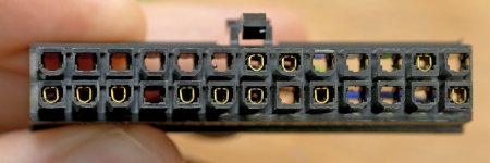
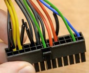
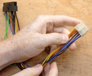
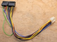
In summary, it seems that Von used the simplest implementation, leaving the Seasonic inside its housing and using wire ties to mount it inside the SE/30's PSU enclosure.  Von pulled out the appropriate 10 wires from the WHITE 24-pin ATX connector of his Seasonic and retained the terminals, then pulled out all 10 wires from his SE/30 PSU's 10-pin connector, and finally plugged in the 10 wires removed from the Seasonic ATX plug, which works because the terminals are the same size.  This leaves you with a single 10-pin white connector coming off your new Seasonic PSU from within the stock Sony or Astec PSU chassis, and that connector in turn attaches to the Analog Board.  Von shorted the Seasonic's GREEN wire to Ground (without which, it won't power ON), then wired the AC wires to the SE/30's power switch via connector he purchased (which isn't absolutely necessary as you could just cut, solder and heat-shrink for the simplest implementation). Close up the PSU chassis, mount, test, and you're good to go.

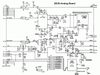
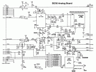
I should add that if you use an internal HDD, you would use the standard 4-pin HDD power harness between your HDD and Analog Board as usual.  There is another way though.  Note the schematic below is of the Analog Board and the bottom left section shows the HDD 4-pin power plug and how it splits off to the CPU Board (motherboard) plug.  Since the Seasonic already has a 4-pin HDD power plug, you technically could use that to power your internal HDD without pulled HDD power through the Analog Board.  That Seasonic 4-wire cable would just be a bit short, but you could use some of the spare Seasonic wire you don't need to extend the cable length using solder and heat shrink tubing.  You'd also probably need to make another hole in the stock PSU chassis to get those 4 wires out.  Overall, it's probably more trouble than it's worth but I mention it since it technically will work fine.

Now on to getting my own SE/30 back in working order!

SE-AnalogBoard_Complete.gif


superjer2000

Well-known member
I tested my Seasonic with HDD in a room that was around 30°C, so my temps were hotter as a result.
It's still very odd that your unit was cycling its fan on and off then.  If your temps were hotter, and if there is a temperature sensor, I would have expected your fan should have stayed on.  Once my fan turned on, it stayed on for quite some time and only turned off for a short time before starting back up and staying on.


superjer2000

Well-known member
It's still very odd that your unit was cycling its fan on and off then.  If your temps were hotter, and if there is a temperature sensor, I would have expected your fan should have stayed on.  Once my fan turned on, it stayed on for quite some time and only turned off for a short time before starting back up and staying on.
@JDW  I just opened up one of my new PSUs (not the one I was testing with the hard disks) and found that the fan had cold solder joints to the point where the solder had cracked quite badly.  I haven't fired this unit up yet, but I wonder if your supply has the same issue which might explain why the fan isn't running continuously as expected...  I'm kind of disappointed as Seasonic is usually one of the highest rated PSU makers.


JDW

Well-known member
I opened my Seasonic and I do NOT see any cracked solder joints.  I specifically looked at the 2 pins on the little PCB from the connector that leads to the fan, and I don't see any problems there.  Have a look yourself at Flickr Seasonic Photo Album.

And here's a YouTube Video I just made showing temperatures and the fan behavior.

Thoughts?


JDW

Well-known member
Since no one shared any thoughts pertaining to my previous post I will share more of my own thoughts, or rather, test data that will server as the definitive word on the subject.

I conducted temperature tests at the office during my work day toady, starting off with only 1 HDD attached, and then after 6 hours of testing I added a second HDD (SATA connector).  There is nothing special about using an HDD.  They merely acted as a Load on the PSU.  Here is the data:

TIME       SEASONIC TEMP.     AMBIENT TEMP.      SEASONIC FAN 
0h:0min    29.7°C 29°C OFF
0:05 32.1°C 29°C OFF
0:10 34.8°C 29°C OFF
0:20 38.5°C 29°C 5s ON (spinning), 18s OFF
0:40 39.0°C 29.5°C 5s ON, 10s OFF
1:35 38.9°C 29.5°C 7s ON, 8s OFF
3:30 39.2°C 30.0°C 8s ON, 8s OFF
6:00 39.2°C 30.0°C 8s ON, 8s OFF
(Added 2nd HDD to SATA power connector)
6:01 37.0°C 30.0°C Continuous Fan (fast at first, then slowed)
8:40 36.1°C 30.0°C Continuous Fan (slow, quiet)


So it would seem there is nothing wrong with my SEASONIC, and I would suspect that if you run similar tests you will find similar results in terms of temperatures and how the fan responds.

The next step is for me to get it fitted into my SE/30.


trag

Well-known member
When considering the ASTEC version of the SE/30 PSU and the 1.25A SWEEP output, there's actually more to it than a single diode.  The single diode being talked about is likely D14, but as you can see below, that diode merely links the SWEEP output to the +12V 2.1A output.  I've not had time to do a complete analysis of the entire circuit, but when examining the output portion, it certainly looks like high-going voltage spikes from the +12V 2.1A output are being clamped to the SWEEP line via D14.


Another way of looking at it is that D14 keeps the Sweep voltage from going lower than the other 12V rail minus D14's Vf...    Late, but I was reviewing the thread, and that just occurred to me.


superjer2000

Well-known member
In addSince no one shared any thoughts pertaining to my previous post I will share more of my own thoughts, or rather, test data that will server as the definitive word on the subject.

I conducted temperature tests at the office during my work day toady, starting off with only 1 HDD attached, and then after 6 hours of testing I added a second HDD (SATA connector).  There is nothing special about using an HDD.  They merely acted as a Load on the PSU.  Here is the data:

TIME       SEASONIC TEMP.     AMBIENT TEMP.      SEASONIC FAN 
0h:0min    29.7°C 29°C OFF
0:05 32.1°C 29°C OFF
0:10 34.8°C 29°C OFF
0:20 38.5°C 29°C 5s ON (spinning), 18s OFF
0:40 39.0°C 29.5°C 5s ON, 10s OFF
1:35 38.9°C 29.5°C 7s ON, 8s OFF
3:30 39.2°C 30.0°C 8s ON, 8s OFF
6:00 39.2°C 30.0°C 8s ON, 8s OFF
(Added 2nd HDD to SATA power connector)
6:01 37.0°C 30.0°C Continuous Fan (fast at first, then slowed)
8:40 36.1°C 30.0°C Continuous Fan (slow, quiet)


So it would seem there is nothing wrong with my SEASONIC, and I would suspect that if you run similar tests you will find similar results in terms of temperatures and how the fan responds.

The next step is for me to get it fitted into my SE/30.
That's an awesome chart! 

Two comments: 

1) When you say there was nothing special about adding a hard disk, it seems as though the PSU does need a load to turn the fan on reliability.  Your initial run of the supply before adding a hard disk resulted in the fan not spinning up at all.  Your data above shows that the fan may not spin reliability with just the load of a single hard disk.  Adding the second hard disk actually resulted in a DROP in PSU temps as the HD added sufficient load.  I can confirm that an SE/30 does put enough of a load on the PSU to ensure that the fan does spin.

2) Your temperature data is pretty close to mine (a few degrees higher but my ambient was way lower).  I would say those seem like normal temps for a small form factor PSU.  I read your original post ("it was very hot to the touch") as indicating that the PSU was running much hotter than that which is why I thought there might be a problem.

Good luck with your install!  I'm currently retrofitting a unit into a IIci power supply and it's not nearly as easy as the SE/30 was.  The mains cable from the Seasonic is too short to reach the unit so I'll need splice in an extension.  

 
Last edited by a moderator:

JDW

Well-known member
Thank you for your kind words.

Please note though that I only added the 2nd HDD a full 6 hours into my test.  With a single HDD in a room that is 30°C (typical for summertime), it took about 20 minutes for the fan to start spinning and even when it did start spinning, it was in ON/OFF cycles.  It was only when I added the additional electrical load of a 2nd HDD that the fan began spinning continuously.  And with a continuous fan running, the temperatures were slightly lower overall and more consistent too.  

It could be that if the ambient temperature was higher, even without the 2nd HDD, the fan might have started spinning continuously.  That is likely if the fan is temperature controlled, rather than load-controlled.


JDW

Well-known member
Fellow SEASONIC users, what are your voltage measurements at the SE/30's external floppy connector?

I get 12.3V, which is good for the 12V line, but all the 5V lines at the floppy connector measure 4.71V.  I never saw voltage drop that low (steady-state) even when I had my old stock PSU's inside.  (My meter's BLACK ground probe was inserted into one of the floppy port connector's bolts.)

SEASONIC open circuit (no load) voltage on the 5V lines is about 5.13V.  (My old SONY PSU's 5V lines measured about 5.45V open circuit.)

I have nothing connected in the PDS slot.  I have all RAM banks filled for a total of 32MB RAM.  No internal HDD.  I am booting off an external SCSI HDD inside an Apple zero footprint HDD enclosure.  Voltages at the floppy connector with the power switched on are the same even without the external HDD connected and without keyboard and mouse connected.  Despite the low voltage, the SE/30 boots just fine and I ran Norton Utilities System Info benchmark app just fine.  I've not yet tested PDS cards.

My Analog Board is stock.  I've not recapped it yet.  SE/30 logic board has been recapped though.

My low 4.71V measurement has me concerned and is why I am curious about YOUR voltage measurements at the external floppy connector.  Just insert a paperclip into the pin hole you want to test if your probe isn't thin enough to fit into the hole, and please let me know if your 5V lines are as low as mine.  I'm concerned that 4.7V is a bit too low.

Thanks.


superjer2000

Well-known member
Hi JDW,

I'm only aware of one pin on the floppy Port that you can measure 5V at (and 2 12V pins) from the Classic Mac Repair Notes guide.  I just checked my Seasonic powered SE/30 at the floppy port ->  Both 12V pins are at 12.30V and the 5V pin is at 4.97V.   Voltage is very stable, (5V moves between 4.97 and 4.98 every so often.)  The Seasonic is in the SE/30 that I still have a hard disk in so there would be a bit more of a strain versus my Antec powered SE/30 that has a SCSI2SD.  My analog board is recapped but I had checked floppy port voltages when I first did this conversion and had the same readings then.  You didn't connect the purple 5V Standby line or one of the orange 3.3V lines to a 5V line when you built your harness, right?  Other possibility (although I'm far from an expert here) might be that the PSU is having trouble regulating the 5V line without any load on the 3.3V rail.  I haven't had any issues with this in my SE/30 or IIcx where I have done Seasonic conversions, but some of the forums I read where guys were using ATX power supplies for bench work had them putting a higher wattage resistor on the 3.3V rail to provide a dummy load to help the PSU regulate itself.  I'm not sure why yours would be any different to mine though...

 
Last edited by a moderator:

JDW

Well-known member
Thank you for the reply. I definitely did not use the Seasonic’s purple wire or the orange 3.3v wires.   After plugging in the appropriate wires into the stock SE/30’s PSU plastic connector, I used my meter to check all of the voltages in that connector on three separate occasions before I even put it into my SE/30. I get 5.13V with the Seasonic in a no load condition, but only 4.7V at the floppy connector when it’s inside my SE/30 and booted. 

I am in Japan and we have 100VAC at 60Hz,   But that small drop in voltage relative to the US should not cause only my 5V line to be low, especially when the 12V line voltage is the same as what you’re reading. 

The screen is bright and I did not notice any glitches or freezes or shutdowns during my testing of the SE/30. I had it booted and running for a couple hours and ran extensive benchmarking repeatedly with Norton Utilities during that time, but again there were no problems. 

I have nothing connected to the 3.3V lines, and since you did not need that resistor, it’s hard to believe mine would need a load resister on them.  If indeed the theory about the load resistor on the 3.3V lines is correct, why then am I able to measure 12.3V at the floppy connector? In other words, if my Seasonic power supply is unstable due to the lack of a load resistor on the unused 3.3V lines, I would expect the 12V lines to be affected as well, but they are not. 

My analog board is not recapped, but you said you checked the voltage at the floppy port before you recapped your analog board and found it to be a rock solid 5V. So I’m not sure what to think. 

Harness4.jpg

Harness3.jpg

Harness2.jpg

Harness1.jpg

 
Last edited by a moderator:

superjer2000

Well-known member
That harness looks right.  A couple of questions:

1) What wires did you use for your harness?  Reason I'm asking is the Seasonic (and ATX wires) are red for 5V, whereas the SE/30's 5V wires were orange.  Your pictures seem to show orange for the 5V lines.  I would have therefore assumed you used the SE/30's harness wires, but it looks like you have a double wire coming out of the Seasonic plug that is capped off, so maybe you swapped in the orange wires from the 3.3V lines to keep it looking original?  Obviously not an issue as the wires are plugged into the 5V positions, but just curious.

2) Is it possible that one of your crimps isn't good, or one of your pins in either harness end isn't making good contact?  If one of your 5V lines has a poor connection and the system is then pulling everything through a single wire, that might cause a voltage drop.

3) it would be interesting if you could measure the 5V at the motherboard connector with the system on (i.e. see if there is anything on the motherboard that is causing this voltage drop).  Also, you could run the system with the power supply not mounted to the analog board, keeping the PSU open and measure the voltage right at the Seasonic PSU connector.

 
Last edited by a moderator:

JDW

Well-known member
Those are definitely RED wires even though there is a yellow color cast on my photos that make them look orange.  Also, all wires you see in the BLACK connector photo are in their original positions EXCEPT for pin-20.  Pin-20 was a BLACK/GND wire before, which I removed and I inserted the other end of the GREEN wire there to ground it.  (You can see the pin numbers on my photo of the black connector if you look closely).  Further evidence that my red wires are indeed red is the fact that I measure 5.13V on those wires open circuit (no load connected).  If they were 3.3V wires, I would not measure 5.13V open-circuit.

The output wires of my Seasonic SSP-250SUB PSU:
Yellow: +12V (I used 1 wire from pin-2 and 1 wire from pin-3)
Orange: +3.3V (I removed all these from the black connector)
Red: +5V (I used 1 wire from pin-9 and the 1 wire from pin-21)
Purple: +5V (I removed all this from the black connector)
Gray: +5V (I removed this from the black connector)
Blue: -12V (I used this from pin-13)
Black: (-) Ground (I used pin-1, pin-5, 2 wires in pin-6 & pin7 -- total of 5 ground wires).
Green: Pin-25, which I connected to pin-20 that was previously GND.  (Shorted to (-) Ground for the PSU to operate.)

I will now need to make additional measurements, and swap the motherboard and analog board to know more.  I will then report back.


JDW

Well-known member
I haven't yet swapped the motherboard or analog board (and my analog board is stock -- not recapped), but this time I put my meter's BLACK Ground probe to a different ground and the voltage level at the floppy connector increased.  So putting your meter's Ground Probe on the screw terminals of connectors on the back of your SE or SE/30 will NOT yield the best ground.  Ditto for the metal tabs that stick up off the back of the motherboard and attached to the metal chassis.

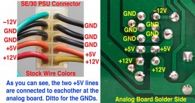
Note the connections (STOCK SE/30 PSU wire colors shown in photo at left below, not SEASONIC wire colors):

SE30_PSU_AnalogBoard.jpg

I measure 5.07V at the back of the analog board when using GND shown above as my Meter's Black Probe GND. (When SE/30 is powered ON, no PDS cards or internal HDD or upgrades, and 32MB RAM -- all banks filled).

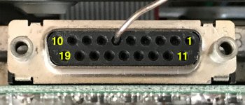
Now note the external floppy connector pin numbers:

FloppyConnector.jpg

With my meter's ground probe connected to a ground point on the back of the analog board, and measuring at the solder side (back side) of the analog board, with SEASONIC as my PSU, I see this:

Pins 10 & 6 (top row) and 15, 16, 17 & 18 (bottom row)= 4.89V, with Ground Probe on analog board solder side GND or on metal chassis where GREEN wire from PSU screws onto it)

Pins 7 & 8 (top row) = 12.33V, with Ground Probe on same point(s) as the 4.89V measurement above.

So I am not getting that amazing 4.97V at the floppy connector like you, but 4.89V is certainly better than the 4.7V I was measuring before with my lackluster ground.  And again, measuring both Positive & Negative at the solder side of the Analog Board shows 5.07V, and I get 5.13V from the SEASONIC open-circuit.


superjer2000

Well-known member
I always use the floppy disk screw terminals for my ground when measuring voltage there and that's how I got my 4.98v. From your testing above it sounds like you did reattach the chassis ground wire?

to confirm, your test was to probe the 5V lines at the floppy port and with your ground probe at the ground points on the analog board?  It still seems like a wire harness issue somewhere then to me. Your results seem like you would measure resistance between the floppy screws terminals (or other motherboard ground points and PSU ground and there shouldn't be any. 


JDW

Well-known member
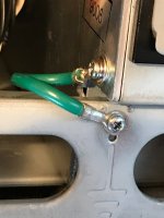
Yes, the green PSU GND wire is securely screwed to the PSU chassis and the SE/30 chassis as shown in this photo:

PSU_GND.jpg

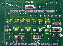
Yes, in my previous post I put my meter's BLACK GND probe to the GND solder joints on the back of the analog board, at the PSU power connector solder joins, to get a good ground.  And this morning I measured all pins of the 14-pin connector at the back of the SE/30 Motherboard (the harness that leads from the Analog Board to the Motherboard), which you can see in the photo below:

BackOfMotherboard.jpg

To get those measurements shown in the above photo in yellow, I put my meter's Black GND probe to one of those GND pins shown in yellow.  And yes, I changed my meter's GND probe to different GND pins shown in yellow, and yes, the voltage measurements where the same, proving that all those GND points there are the same.

And of course, the SEASONIC is powering all of this.

Note in the analog board schematic P4 (top left), which matches pins in the 14-pin connector shown in the photo above.

SE-AnalogBoard_Complete.gif

Von, you have a SEASONIC.  Could you please check your voltages for us?  Thanks.

 
Last edited by a moderator:

JDW

Well-known member
4.83V was what I measured 11 years ago when I was using my stock SONY PSU to drive all manner of upgrades:


Top