• Updated 2023-07-12: Hello, Guest! Welcome back, and be sure to check out this follow-up post about our outage a week or so ago.

Recently-recapped SE/30 went "bang" - a tantalum-capacitor cautionary atle

halkyardo

Well-known member
So, the other day, while I was using it, my SE/30 experienced rather a dramatic failure, dying with a sharp "snap" and a smell of burning electronics.

I'd recapped it about a year ago with tantalum capacitors, but I hadn't touched the (Sony) power supply or analog board, so my first instict was to tear those down and look for failed components.

Bzzzt. Wrong.

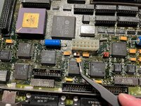
After staring at the power supply and analog board for a while with no obvious clues, I thought I'd shelve it for now and started putting it back together... at which point I finally looked at the logic board, and saw that the top of C9 had been blown clean off! Yikes!

It's a weird failure - I know that using 16V tantalums on the + and - 12V lines is a little bit dodgy, but my understanding was that was more out of concern for long-term life of the capacitor than a risk of near-immediate failure! In the year since I recapped it, it's probably seen a few tens of hours of use - more than many vintage computers, I'm sure, but little enough that I think it's safe to call it a premature failure.

Out of an abundance of caution, I have also removed C10 (C9 is the main filter capacitor for the -12V line, C10 is its +12V counterpart); the machine runs fine without them, but I'll be replacing them with higher-voltage-rated parts to avoid a repeat of this.

Anyway, let this be a warning that it CAN happen to you! Choose your replacement capacitors with care!
1705874088259.jpeg

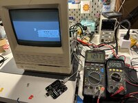
Another interesting thing to note - I probed voltages at the power supply connector, and while the +5V rail was more or less spot-on, +12V was noticeably high at 12.7 volts! I'm assuming that this is at least in part because I'm using a BlueSCSI and don't have a spinning hard drive loading down the +12V rail, but I can't imagine that's good for things - would it be worthwhile to tweak the power supply's regulation adjustment down a bit and maybe end up with the +5V rail a bit below spec, or just leave it as-is?
1705875756449.jpeg
 

halkyardo

Well-known member
Do you think this happened because 16v on a 12v rail is not derated enough for a tantalum?
I'll admit that I don't have a solid handle on the theory behind tantalum derating, but the general rule of thumb seems to be that the steady-state voltage across them should be no more than 50%-80% (depending on who you ask) of the rated voltage. So at best, 12 V is cutting it a bit fine, and at worse is way too much.

The mechanism of failure is fascinating - tantalum capacitors can 'self-heal' damage to their dielectric - thin spots or impurities will conduct more current, which causes localised heating that in turn starts an oxidation reaction that 'heals' the dielectric. But when the damaged area is large, the heat will break down the dielectric before the self-healing reaction can take place, so you get a thermal runaway situation.

I suspect that in my case, the failure was accelerated by overheating during soldering (I was rather out of practice at the time and was a bit ham-fisted about it), and it had just been gradually cooking away ever since.
 

JT737

Well-known member
The unfortunate thing with Tantalum caps is that when they fail, they usually fail with a "bang". This is why I don't use them anymore. I prefer polymer capacitors-they are safer (at least from what I've seen) and seem to be much more voltage tolerant than tantalum capacitors.
 

Phipli

Well-known member
would it be worthwhile to tweak the power supply's regulation adjustment down a bit and maybe end up with the +5V rail a bit below spec, or just leave it as-is?
Leave it as it is. The 12v is always high, the 5V is vastly more important than the 12V.

The 12V only runs... what, the fan and some stuff that is regulated elsewhere? Not much.

The 5V runs all the logic, CPU, video... Things stop working, temporary or permanently, if you put the 5V out by too much. Also "too much" isn't much at all. 2% low is probably the limit for the 5V - they perhaps handle a bit more above, but basically I'd stick to between 4.9 and 5.1V. Higher is better in the range.
 

Phipli

Well-known member
Do you think this happened because 16v on a 12v rail is not derated enough for a tantalum?
The datasheets for tantalums that I've seen basically say the labelled voltage on the part should be double the operational voltage. So for 12V, you should fit 25V parts.

I had to go back and rework some of my boards, including my dad's SE/30.

The good news is you can use 25V tantalums for 5V circuits too, as the characteristics don't change as much with voltage as some capacitor types.

I kind of wish they'd just renamed them, so a 12v part is labelled 12v.
 

halkyardo

Well-known member
The unfortunate thing with Tantalum caps is that when they fail, they usually fail with a "bang". This is why I don't use them anymore. I prefer polymer capacitors-they are safer (at least from what I've seen) and seem to be much more voltage tolerant than tantalum capacitors.
Yeah, when I plugged my IIfx back in after 10 or so years in storage, one of the tantalums on the 12V rail let out some proper fireworks, left a big scorch mark up the back of the case. All fixed now, but definitely not one of my more enjoyable retrocomputing moments.

Leave it as it is. The 12v is always high, the 5V is vastly more important than the 12V.

The 12V only runs... what, the fan and some stuff that is regulated elsewhere? Not much.

The 5V runs all the logic, CPU, video... Things stop working, temporary or permanently, if you put the 5V out by too much. Also "too much" isn't much at all. 2% low is probably the limit for the 5V - they perhaps handle a bit more above, but basically I'd stick to between 4.9 and 5.1V. Higher is better in the range.
Yeah, I'm generally not keen on messing with adjustments without good reason, so knowing I can leave it alone is a relief.
 

jmacz

Well-known member
The datasheets for tantalums that I've seen basically say the labelled voltage on the part should be double the operational voltage. So for 12V, you should fit 25V parts.

I had to go back and rework some of my boards, including my dad's SE/30.

It's interesting that the kits still include the 1:1 labeled tantalums (like from console5). I picked up a double rated one for my IIfx based on feedback. But will need to take a look at my SE/30 which came pre-capped with 16V tantalums (outside of the one 50V one).
 

croissantking

Well-known member
+1 for polymer caps, they don't suffer from this problem, and they retain the look of the original electrolytic caps.
I’m going to stick to fluid-filled electrolytics or polymers as I have been. Polymers are dearer, so I’ll just use them on more premium items. I only used tantalums on one occasion, for my SE/30 Reloaded builds.
 

LaPorta

Well-known member
Ahh British expression! I think what we need are text-based accents so we know who is from where :p
 

Scott Baret

Well-known member
Count me in as another one who no longer likes the idea of tantalum caps.

Some years ago, I posted about a re-capped LC having some video interference issues. The LC had tantalum caps on its board and I believe they may have been a little off from the original values. After switching to something more conventional (don't remember if they were polymer or not), the interference stopped. I tried to blame the PSUs on it and went through several of them, only to realize they weren't the issue. I knew the video chip was good, too.

The computer has not had any such issues since the cap switch was made. I also had an issue with a Classic acting up with tantalums at one point and no longer use or recommend them.
 
Top