• Updated 2023-07-12: Hello, Guest! Welcome back, and be sure to check out this follow-up post about our outage a week or so ago.

Modern PSU for the SE/30

trag

Well-known member
So here's a build log, perhaps this will help others wishing to do the same:

Now that I have a nice terminal crimper, I wouldn’t have removed the terminals from the ATX connector.


Nice explanation.    Thank you!

Which terminal crimper did you choose?  Did you try more than one?   I'm in the market for one, but there's a dizzying array.  I should probably consult with the hardware guys in the lab upstairs at work...   But they have a little different focus than us hobbyist users.

Are you quoting yourself or someone else about dissecting the Sony PSU and finding just a single isolation diode on the 12V rail?

The reason I ask is that I wonder if the rail was 12V before the diode or 12V after the diode.    Vf is going to cut .7V - 1.3V off of the voltage.    If the rail must be 12V after the diode, that's inconvenient.   If the sweep will tolerate the loss, then I see no reason not to add a diode on the wire to the sweep.    Covering the amperage will be  a little challenging.   Was it close to 3A?

 
Last edited by a moderator:

JDW

Well-known member
Which terminal crimper did you choose?  Did you try more than one?   I'm in the market for one, but there's a dizzying array. 
But even if you have a terminal crimper, you would also need to buy appropriately sized terminals that would be an exact fit for the plastic connector you intend to use.


JDW

Well-known member
...I wonder if the rail was 12V before the diode or 12V after the diode.    Vf is going to cut .7V - 1.3V off of the voltage.    If the rail must be 12V after the diode, that's inconvenient.   If the sweep will tolerate the loss, then I see no reason not to add a diode on the wire to the sweep.    Covering the amperage will be  a little challenging.   Was it close to 3A?
When considering the ASTEC version of the SE/30 PSU and the 1.25A SWEEP output, there's actually more to it than a single diode.  The single diode being talked about is likely D14, but as you can see below, that diode merely links the SWEEP output to the +12V 2.1A output.  I've not had time to do a complete analysis of the entire circuit, but when examining the output portion, it certainly looks like high-going voltage spikes from the +12V 2.1A output are being clamped to the SWEEP line via D14.

AstecPSU-outputs.png.28f42ceadb6978da968156214f63f00e.png


joethezombie

Well-known member
Which terminal crimper did you choose?  Did you try more than one?
I bought one just like this from ebay.  I haven't yet used it enough to really give an opinion.  I've crimped some small terminals for an ADB project using digikey WM14852 and WM4561CT-ND, and that's about it, but they did a very neat, professional looking, and (more importantly) well-working job.

But even if you have a terminal crimper, you would also need to buy appropriately sized terminals
Right, but most of the molex terminals are "universal" per se, as the ones from the FSP220 fit and locked into the old SE-SE/30 connector without issue.  The same (a guess, I didn't buy one) connector can be found at digikey with WM3704-ND, which also lists compatible terminals.

Are you quoting yourself or someone else about dissecting the Sony PSU and finding just a single isolation diode on the 12V rail?
"Dissecting" is definitely much to strong a word.  I should also clarify it wasn't Sony, rather Astec, as referenced in the photos.  While musing around looking for a modern replacement, I was curious why I couldn't just use a single 12V supply, so I started sketching out the circuit from the outputs working back to spot the differences.   Keep in mind, this was on a non-working unit, so I have no voltage measurements.  Anyway, this turned out to be a partial effort-- after finding the FSP220 with two 12V rails, I just went with that and never went back to complete/verify.  Apologies my quickly typed sentence had such a strong inference.

When considering the ASTEC version of the SE/30 PSU and the 1.25A SWEEP output, there's actually more to it than a single diode.
Thanks for posting, I remember having a difficult time trying to find the schematics when I searched.  I see the complete schematics have now been linked recently.


trag

Well-known member
But even if you have a terminal crimper, you would also need to buy appropriately sized terminals that would be an exact fit for the plastic connector you intend to use.


They're usually Molex connector housings, and once one identifies them on Digi-Key, the product page will yield links to compatible pins and mating housings.   So finding the right pins is not usually a problem.   Plus, all the Mini-fit Jr. housings use the same pins, and every power cable connector I've seen so far (at last the two row ones) are Molex Mini-fit Jr. line.    It could be a problem for some connectors, but I haven't run into a problematical one yet.    Of course, I haven't been doing much of that kind of running the last 10 years.


JDW

Well-known member
With regard to crimping, isn't it more trouble than it's worth?  You need to buy the correct crimper tool, then buy the correct terminals, then make sure you have the means to remove the terminals from your existing connector.  And if like me you live outside the US and decide to buy all that from the US, you have international shipping charges with which to contend.

Wouldn't it just be easier to cut off all the wires from a connector on your new PSU, then slip on some heat-shrink tubing on each wire, then cut off the stock SE/30 connector but leave 10cm or so of wire length dangling, then solder the appropriate wires together, then slide over the heatshirink tubing and shrink it?  Wire insulation colors will be different, but Steve Jobs won't be looking, so it's okay! :)


trag

Well-known member
Wouldn't it just be easier to cut off all the wires from a connector on your new PSU, then slip on some heat-shrink tubing on each wire, then cut off the stock SE/30 connector but leave 10cm or so of wire length dangling, then solder the appropriate wires together, then slide over the heatshirink tubing and shrink it?  Wire insulation colors will be different, but Steve Jobs won't be looking, so it's okay! :)


Not satisfactory to my OCD impulses.    Plus, with practice, crimping the pins isn't that difficult.   Crimpers are (or can be) more or less universal.  They have different imprints for different diameter "legs".   So getting the right one isn't really an issue.   It's more a matter of there being a myriad of crimping tools, with varying degrees of comfort and convenience.

I find it easier to just buy new housings rather than try to salvage old housing by removing the pins.  They're not pricey.

Being outside the USA puts a different dimension on it though.


superjer2000

Well-known member
I was finally able to finish this mod.  I ended up ordering two different power supplies and ended up starting with the easier one to retrofit first.

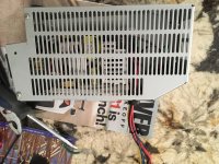
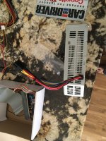
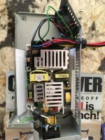
This time, I used a Seasonic SSP-250SUB.  This supply serves up the right power mix and has the added benefit of being modular so that you don't have the rats nest of wires coming out of the supply, but instead a 26 pin molex connector.  When I took it apart, the added benefit was that the power plug wasn't soldered in like on the other supply I bought and instead just had to be unplugged from the power board and slipped through the back of the supply on disassembly.

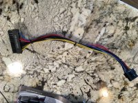
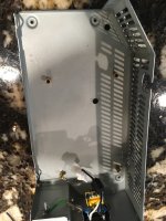
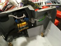
I took out all of the pins from the 26 pin molex connector and just re-wired back in the pins I needed.  I bought a crimpling tool and some 10 pin molex plugs to match up with the SE/30's analog board plug.  I ended up wiring the power switch on the SE/30 to the Power On/Ground rather than switching the power from the wall.  I used brass standoffs to mount power supply PCB, similar to what was done above.

I'm not sure if there is any independance between the "two" 12V rails (There was no resistance between any of the 12V wires) but I sent +12V from the main motherboard connector to one 12V pin on the SE/30 connector and the other 12V from a 4 pin motherboard connector to the other 12V pin on the SE/30.

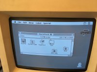
I tested the power supply with a couple of hard drives before placing into the Mac and then removed the hard disk molex cables from the power supply before finalizing.  System booted up the first time and voltages seem rock solid when tested through the floppy port (whether hard disk / floppy etc. are being accessed).  I still need to recap the analog board.  The system is brighter than it was (still not as bring as it should be) and there is some ghosting of the images where there are window title bars or when menus are pulled down.

IMG_2885.jpgIMG_2886.jpgIMG_2890.jpgIMG_2898.jpgIMG_2899.jpgIMG_2902.JPG

IMG_2896.jpg


Trash80toHP_Mini

NIGHT STALKER
Most excellent! That vented side panel is pretty interesting, mine (SE/30 & SE) have solid side panels thermal pasted atop the heatsinks in the PSU. Who made that particular PSU and are they common?


JDW

Well-known member
Interesting.  The Seasonic is an “industrial” power supply.  Specs are clearly more than adequate in terms of current capability which makes me wonder about that cause of the ghosting.  I assume you did not have any ghosting with your old power supply?

joethezombie, do you have any ghosting with your new power supply? 


superjer2000

Well-known member
Interesting.  The Seasonic is an “industrial” power supply.  Specs are clearly more than adequate in terms of current capability which makes me wonder about that cause of the ghosting.  I assume you did not have any ghosting with your old power supply?

joethezombie, do you have any ghosting with your new power supply? 
I did have ghosting before. Based on some research I did I think it's the CRT. I did this mod on this SE/30 rather than my good SE/30 with a perfect screen just in case it started on fire. :)   The screen is brighter than before though. 


superjer2000

Well-known member
Most excellent! That vented side panel is pretty interesting, mine (SE/30 & SE) have solid side panels thermal pasted atop the heatsinks in the PSU. Who made that particular PSU and are they common?
It's an Astec. My other SE/30 to be worked on next is a Sony PSU. 


Von

Well-known member
I was finally able to finish this mod.  I ended up ordering two different power supplies and ended up starting with the easier one to retrofit first.

This time, I used a Seasonic SSP-250SUB.  This supply serves up the right power mix and has the added benefit of being modular so that you don't have the rats nest of wires coming out of the supply, but instead a 26 pin molex connector.  When I took it apart, the added benefit was that the power plug wasn't soldered in like on the other supply I bought and instead just had to be unplugged from the power board and slipped through the back of the supply on disassembly.

I took out all of the pins from the 26 pin molex connector and just re-wired back in the pins I needed.  I bought a crimpling tool and some 10 pin molex plugs to match up with the SE/30's analog board plug.  I ended up wiring the power switch on the SE/30 to the Power On/Ground rather than switching the power from the wall.  I used brass standoffs to mount power supply PCB, similar to what was done above.

I'm not sure if there is any independance between the "two" 12V rails (There was no resistance between any of the 12V wires) but I sent +12V from the main motherboard connector to one 12V pin on the SE/30 connector and the other 12V from a 4 pin motherboard connector to the other 12V pin on the SE/30.

I tested the power supply with a couple of hard drives before placing into the Mac and then removed the hard disk molex cables from the power supply before finalizing.  System booted up the first time and voltages seem rock solid when tested through the floppy port (whether hard disk / floppy etc. are being accessed).  I still need to recap the analog board.  The system is brighter than it was (still not as bring as it should be) and there is some ghosting of the images where there are window title bars or when menus are pulled down.

View attachment 23279
OK, I am in.  I just ordered one of these from NewEgg.com for just under $50 shipped to deal with my leaky PSU. It will arrive early next week and this should be a fun project.

Does anyone have a diagram that maps the colored wires from the original PSU to their needed voltages?

Here is what I have:

BK, BK, BK OR, YW

BR, BK, BK OR, RD

THx!


JDW

Well-known member
OK, I am in.  I just ordered one of these from NewEgg.com for just under $50 shipped...
Could you please provide a link?

I'm thinking about buying at least one, possibly two, but I need to get them shipped to me in Japan.  Curious if NewEgg would do that.

Thanks.


JDW

Well-known member
Well, I finally found the Seasonic SSP-250SUB PSU on EBAY, and thankfully they ship to Japan and will combine shipping for multiple units.

That Seasonic PSU also seems to have a Fanless Mode.

Is there a switch on it to set the mode, or does it just shut-off the fan when at 30% or less of maximum load?

 
Last edited by a moderator:
Top