• Updated 2023-07-12: Hello, Guest! Welcome back, and be sure to check out this follow-up post about our outage a week or so ago.

Modern PSU for the SE/30

JDW

Well-known member
This post by Wally back in 2012 details technical requirements of the SE/30 PSU (please read it).

Note that Wally says there is a “4A peak load” requirement on the +12v output, and the separate +12v SWEEP has a tight +/-10mV voltage tolerance (which sounds a bit too tight to me, so maybe he read the book wrong).

As mentioned earlier, ARTMIX advertises the following specs on their 2009 edition PSU:

5V @14.5A

+12V @3.75A

+12V SWEEP @>3A

-12V not listed, but shows as 0.5A in photo of 2006 model label

Thanks to Joe, we know the 2009 ARTMIX PSU contains a Mean Well PPT-125B that shows these specs:

5V @11.5A

+12V @3.00A

-12V @0.5A

ARTMIX has posted the 5V@“14.5A” lie/error since 2009.

If +12V really does peak at 4A, Like Wally said, depending on the duration of the peak, it would seem most prudent to have a +12V output that is capable of 4A or more.

The ARTMIX PSU also uses a little custom PCB built with a LT1268 switch-mode controller. If ARTMIX used the Typical Application example circuit shown in the LT1268 datasheet, then the little PCB converts “up to 1.5A” of the Mean Well’s 5V@11.5A output to become the +12V SWEEP output, leaving 10A for the 5V output.

If so, that would be the second lie/error, since the 2009 ARTMUX PSU advertises “12V SWEEP @>3A.”

If indeed there is a +/-10mV tolerance on the SWEEP as Wally contended back in 2012, the LT1268 is almost certain NOT to satisfy such as the peak-to-peak ripple is likely more than 20mV.  But even if we assume there is no 10mV tolerance requirement on the SWEEP output, the fact remains that the specifications advertised for the ARTMIX PSU are inaccurate, and the +12V@3A output may be inadequate. These are important considerations for anyone considering purchase of the ARTMIX PSU, especially because it sells for a whopping $200+shipping.

Here are the specs of the stock SONY SE/30 PSU (CR-44, 699-5047) for reference:

5V @6.0A

+12V @2.1A

+12V SWEEP @1.25A

-12V @0.5A

Special thanks to omidimo for the lovely photos and kind words about my Flickr photos, and to joethezombie for excellent info, and to superjer2000 for alerting me to that old thread and Wally’s post, and to the rest of you contributing to this thread.

Right now, I am leaning toward the purchase of the power supply used and recommended by joethezombie.  What’s funny is that ARTMIX could offer a better product and still make a huge profit just by purchasing the FSP220-60LE for use in a 2018 edition SE/30 PSU!  Have a look at the specs:

FSP220-60LE

5V @16A

+12V1 @16A

+12V2 (SWEEP) @10A

-12V @0.8A

Sadly, the only "economically priced" FSP220-60LE I see sold on Amazon Japan (relevant to me because I live in Japan) is clearly a Chinese version of the original that is not the same as the original.  Have a look:

https://www.amazon.co.jp/ユニバーサル小型シャーシ-FSP200-50PLA-FSP180-50PLA-FSP250-50PNA-1台の機械、産業制御、カラオケ機、キャッシュレジスター、POS機械、1Uサーバー、NASサーバー/dp/B077BR1W2Q/

Lastly, please let me know what that “soft mod” is.  Thanks.

 
Last edited by a moderator:

superjer2000

Well-known member
I was looking at the FSP220-60LE but ended up just buying an Antec MT-352 for $71CAD which has the following specs:

5V @ 20A

12V1 @ 18A

12V2 @ 18A

-12V @ 0.8A

I also bought some 10 pin modular plugs that I'm hoping will fit the SE30 analog board, 24 pin ATX plugs and the relevant modular plug pins.  When it gets here, I'll assess if I try to mount the Power supply in its current case somehow or take it out and try to put the guts into the old power supply case.  I'm pretty excited about this project, I hadn't even considered the possibility of doing anything besides recapping the old supply. If it works, I'll do my second SE/30 and a couple of SEs that I have as I bought enough connectors and misc. parts to do ~10 units.  I'm not sure if there will be any concerns regarding lack of load on the supply. 

 
Last edited by a moderator:

Trash80toHP_Mini

NIGHT STALKER
p.259 of GttMFH2e to which wally was referring says:

Parameter                               Specification

+12 volt sweep supply          11.5V - 12.5V

Ripple and noise are beyond my ken, but it makes sense to me that while the sweep voltage can vary within the spec above, whatever the value may be at any given time between 11.5V and 12.5V it shouldn't waver from within the tight limits he posted to prevent the raster image from appreciably shrinking or expanding in the user's view while the Mac's banging on the other rails of the power supply for whatever purposes.


joethezombie

Well-known member
Lastly, please let me know what that “soft mod” is.  Thanks.


There was a speculation thread at one time I can't locate now (perhaps another lost soul?) about converting an SE/30 to use soft-power on and off like his big boxen brethren.  This was thought possible because the documentation on the PDS slot of the SE/30 specifies on pin C1, the /PFW signal is present.  Normally /PFW is always high, but when one selects Shut Down from the menu, it turns low to indicate Power Fail Warning to any cards connected to the bus.

Modern ATX/ITX power supplies are always on, and supply +5V standby voltage at all times.  After an ATX conversion, this standby voltage could be used for the power key on the keyboard, and turn the SE/30 on automatically when pressed.  (For the supply to turn fully on, we ground the PS-ON pin.)

Now that that SE/30 is on, pin C1 on the PDS slot could then be monitored for when the Shut Down command is issued, and automatically power down the power supply back to standby voltage.

Unfortunately, the documentation proved incorrect, and the /PFW signal never goes low on the SE/30.  This made a lot of individuals sad.  Speculation occurred we could pull that signal from where it originates, but the details are lost, or my search-fu is faulty.  I haven't looked further to see if that signal is present at another location on the logicboard.


Trash80toHP_Mini

NIGHT STALKER
Can't really see, is the rocker switch missing from omidimo's PSU? I don't like leaving anything plugged in and "always on" when it comes to hacked equipment.

Would it be possible to use the standard switch to cut AC power on and off as usual, but add a circuit to provide the momentary blip needed to actuate ATX powerup when the main switch is flipped to the on position? Is such a thing even necessary?

 
Last edited by a moderator:

joethezombie

Well-known member
Nah, the rocker switch is still there, its just below the power plug socket, hiding behind the heatsink.  I permanently shunted the PS-ON pin to ground, and just use the rocker switch like normal, no momentary blip needed.

EDIT: Just for clarity, the rocker switch is used as mains switch, just like normal.  When it's off, there is no standby voltage because there is no voltage period.

Tomorrow I shall open it up and take pictures of the standoffs, the power connecter I built, and how to shunt the PS-ON so it turns on/off with the rocker switch.

 
Last edited by a moderator:

JDW

Well-known member
I was looking at the FSP220-60LE but ended up just buying an Antec MT-352 for $71CAD which has the following specs:

5V @ 20A

12V1 @ 18A

12V2 @ 18A

-12V @ 0.8A
Specs are nice, but the price isn't so nice for me in Japan.  Amazon lists the same PSU for roughly US$135. :-(

There was a speculation thread at one time I can't locate now (perhaps another lost soul?) about converting an SE/30 to use soft-power on and off like his big boxen brethren... Unfortunately, the documentation proved incorrect, and the /PFW signal never goes low on the SE/30.  
I use a Sophisticated Circuits PowerKey Pro 600 ADB, so I technically don't need Soft Power in the SE/30.  However, the PowerKey only works in System 7 or higher, so if a hardware solution for the SE/30 could be found that allowed Soft Power in System 6 too, that would be superb!

Tomorrow I shall open [the FSP220-60LE] up and take pictures of the standoffs, the power connecter I built, and how to shunt the PS-ON so it turns on/off with the rocker switch.
I look forward to seeing those photos, Joe.  But basically it seems you leave the FSP220-60LE's power switch attached but always in the ON position (which is obviously needed), and then you shorted something called "PS-ON" to ground so that the SE/30's power switch will turn it ON/OFF.  Understood.  The rest of your implementation will hopefully become clearer when I see your forthcoming photos.  Thanks!


Trash80toHP_Mini

NIGHT STALKER
Just opened up my SE's Sony PSU, never realized the side of the case acts as a heat spreader. Have we had any schematic data developed on the Sony?

Need a pic of the PSU you're considering right about here in the thread. [;)]

The following is based on my meager understanding of what I've seen in a couple of ATX PSUs I've cracked for my IIsi PSU rebuild:

Been thinking about tolerances on sweep voltage, can't we add a bigass cap to one of the PSU's 12V output lines to even it out to meet those tight variance specs?

Looks like there'll be enough area above the PSU to mount a PCB to the side with that cap, joe's shunt, headers for plugging in the stock AC connector harness with its ferrite ring. A fused passthru with solder points for the AC wiring coming from the PSU connector/whatever would be at that end. Bigass cap wherever and at the front of the PCB you'd have solder points for clipped wiring from the PSU outputs. Desoldering redundant leads from the PSU PCB seems like the easiest route to cleanup.

Dunno if it's just me, but for a step by step howto, showing which lines to clip to specified lengths and where to solder them into thruholes on an adapter PCB seems easiest.  I'd think it'd have to be the most reliable form of wiring connectionc (HATE splicing) and would provide easily defined test points for a novice to meter.

Step by step instructions for desoldering redundant wiring from the PSU would definitely be safest (HATE hanging wires with electrical tape on 'em, even at low DC voltages) and wiring clutter reduction would reduce resistance to convection airflow. That horrid wiring dam at the front of the Artmix PSU give me the heebie-jeebies.

Is there a PCB house that'll do inexpensive runs of the thick, single sided PCBs with thick copper traces for PSU current? We can gang several of the narrow adapter PCBs on one blank.

 
Last edited by a moderator:

Trash80toHP_Mini

NIGHT STALKER
@Bolle and joe: have we got data on where /PFW goes on the ProtoCache1 adapter design and what it might be doing? If it's not really used for anything other than stabilizing the signal on the adapter side the source of the pullup ought to be easily identified on the two schematics we've got available. Adding the pullup to the full height adapter would isolate it nicely for motherboard side playtime.  [;)]

 
Last edited by a moderator:

joethezombie

Well-known member
/PFW does nothing.  It's just always high.  Must of been in Oregon too long.  It would be just a straight through connection to the THRU slot on the ProtoCache, and doesn't exist on the CACHE slot.

DCaDftMF states:

*On the Macintosh SE/30, this signal name has been referred to as PWROFF, but its function is the same on both theMacintosh IIsi and the Macintosh SE/30.


But this is a lie.  It serves no function on the SE/30.  (I hooked up my logic analyzer to the C1 pin, and it never changes until one flicks the power switch to off)

 
Last edited by a moderator:

Trash80toHP_Mini

NIGHT STALKER
Did you try grounding the line to see what happens when it goes low? I wonder how it's implemented in the IIsi now. I'll take a look at the three available schematics and docs, maybe I can come up with something crazy. :blink:

Offhand, hacking the system shutdown command so it triggers an ADB powerdown event would sidestep the immovable /PFW signal issue. Blipping the switch in the ATX PSU circuit via that generated ADB event would mimic the KBD power key from the Mac side in place of displaying the "it's safe to power down you macintosh" dialog box.. Coupling that kluge with the Power Key event on the other side via an internal ADB signal tap comes to mind. Might need to use diodes or logic to decouple the two ADB event signals of the synthesized soft power down from the Mac dialog side and soft power up from the KBD. That would get around the lack of the "are you sure you want to power down or just restart" dialog from the KBD event. This approach isn't at all kosher, but might it be just good enough if it could be pulled off?

 
Last edited by a moderator:

joethezombie

Well-known member
So here's a build log, perhaps this will help others wishing to do the same:

First thing I did was take the and remove internals of the FSP220 from the casing.  I unscrewed the ground lug and desoldered the leads from the power connector (there is no power switch on this model).  Don’t mix up the neutral and hot leads, definately mark them somehow.  Here it is inside the empty Astec casing for fitment trials:
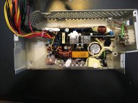
IMG_0426.jpg

Yay, it fits!  So now lets make a method to screw the PCB to the case.  Firstly, bend down the center standoff and make it flat with the case because we wont be using it.  Then, use standard PC motherboard standoffs, drilled and screwed into the casing with the same hole pattern as the FSP220 PCB.  Make sure to leave the clear insulation sheet in place:
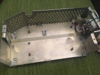
IMG_2030.jpg

Here is the backside of the casing, showing the PC motherboard standoffs drilled through.  The depth was shallow compared to the casings normal standoffs, so there is no clearance issues with stabbing the analog board:
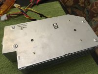
IMG_2036.jpg

On the original Astec power supply, the PCB and the power switch are connected with a cable.  I got the idea to desolder the connector from the old PCB and use it to make a similar plug in cable.  First, solder a white (neutral) and a black (power) appropriately  gauged wire to the bare leads on the FSP220. (Remember we had desoldered them from the power connector earlier, and didn’t mix them up).  After soldering, secure and insulate them with heat-shrink.  Now take the other ends of the wire, and attach them to the that desoldered power connector, and insulate them with heat-shrink.  The green (ground) wire, I was going to attach to the empty pin, but the original power connector is missing the matching terminal inside.  I was going find one to order, but in the end just soldered it directly to the ground lead on the power connector.
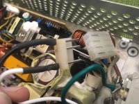
IMG_2034.jpg

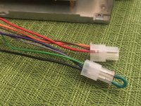
Normally, this style of power supply is operated by soft-power.  A momentary switch on the computer case issues a latch which the motherboard places on the PS-ON pin of the power supply.  Our SE/30 does not have the circuitry to do this, so we need to force the power supply to be on when the switch is on.  We do this by shorting the PS-ON pin (green wire) to GND (black wire).  After placing the small shunt, the power supply will turn on fully as soon as the power switch is flipped on.  You can secure the shunt with a dab of hot glue.  Also in this picture you see the connector with red, brown, and orange wires.  I left this intact for a couple of reasons which I will explain in just a bit.
IMG_2032.jpg

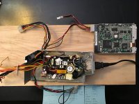
Now we need take the ATX connector from the FSP220 and remove the terminals corresponding to our power requirements.  They make a special terminal removal tool, or you can cheap out and use your wife’s flat sewing machine needle.  I used yellow/black for the 12v Sweep, yellow for the 12v Drive, blue is -12v, red is 5v, and blacks are ground.  Take the old SE-SE/30 connector from the old PSU and remove all the terminals so it is empty.  Now because ATX and the SE-SE/30 connector use the same housing, we can directly place the terminals from the ATX connector into the correct ports.  I also left a Molex and floppy style connector attached for SCSI2SD power:
IMG_0442.jpg

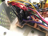
Looking at the above picture, everything to the left that’s in the bread tie needs to be removed.  The best way to do this is by color.  Take everything yellow that you don’t want, and clip them off.  Then place some heat-shrink around the bundle of yellow, and fill the top with hot glue.  Proceed to the next color.  By keeping the colors together, you remove any risk of shorting:
IMG_2035.jpg

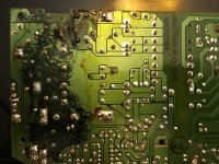
So why didn’t I just recap the existing PCB?  It was ruined due to capacitor leakage:
IMG_0427.jpg

Afterthoughts, notes for next time:

Now that I have a nice terminal crimper, I wouldn’t have removed the terminals from the ATX connector.  I would have just lopped it off and put new terminals on the wires I needed.  Then, I could have had a shorter cable going from the power supply to the analog board.  It’s too long for my liking, but not unwieldy .

I wouldn’t make the little cable to attach the power switch to the PCB.  I’d just solder the power leads directly to the switch.

I left the fan installed for a short while, but ended up clipping it completely out.  Don't forget to insulate the ends of the wire after clipping it out.

I did this back in December of 2016, and I haven't had a single issue.

 
Last edited by a moderator:

JDW

Well-known member
So here's a build log, perhaps this will help others wishing to do the same...
Superbly written and photographed, Joe!  A thousand thanks for your time in doing this.

QUESTION No.1: Regarding your "bread tie" bundle of wires, you suggest cutting them off but then you say to use heat shrink and hot glue.  I'm not clear on your intentions here.  If you don't need wires and potentially won't ever, why not cut them off right at the PCB so there is no chance of shorting and you eliminate all of the wire entire, which means no hot glue or heat shrink would be needed on them at all.  Can you explain?

QUESTION No.2: What drill bit size did you use to cut those 4 holes in the stock metal PSU case?  Since you purchase standards that are "just the right length" and since you are expecting the screw side to keep the new PSU well mounted for years, having the right drill hole size is very important.  (Normally, it would be best to use a longer screw and the apply a nut on the back side, but there is no clearance for the nut, which is why you did what you did.  I might put some superglue on there to absolutely ensure vibrations don't cause the screws to loosen over time.)

QUESTION No.3: Have you used your SE/30 continuously for more than an hour and then felt the PSU (outside of the stock metal enclosure in which the new power supply is housed) to see how warm it gets relative to the stock PSU?  No doubt the new one runs cooler.  I'm just curious.


joethezombie

Well-known member
Answer 1:  The reason I used heat-shrink and hot glue, is because the huge mass of wires make it very difficult to cut off right at the PCB, especially if the removal target is in the middle of the bundle.  It's not as easy as you would think to spread wires and clip at the base with so many in such a small area.   Plus, there is the vertical PCB right next to the wire bundle that makes it very difficult to fit in the nippers.  I didn't want any chance for different voltage wires to be able to short together.  Desoldering can work, but the underside of the PCB is a mess, and if you are not careful, you could definitely cause problems.  If you are able to clip off right at the PCB, do it!  Just don't leave a stub that the insulation could slip off and cause the bare wire to short against the PCB.  There are many voltages in a very small space.

Answer 2: I used a "stepper drill bit" to make the hole larger and larger until the motherboard standoffs self-tapped into the holes.  I did this because I didn't know the size of the standoffs I had on hand.  If you purchased some, they would probably have a specification for proper hole/tap size.   One of the holes I made too big by mistake, but you can use a dab of solder or epoxy to permanently attach the standoff to the casing.

Answer 3: After snipping the fan, I was a bit worried about over heating.  I ran Apple Personal Diagnostics in loop mode all day long.  The casing to the power supply becomes warm, but not as warm as the flyback shielding, and certainly not anywhere near hot.   Coincidentally enough, I just ordered a laser thermometer because I wanted to test the temperature of a Radius Rocket on which I replaced the CPU, so if you give me a week or so, I can take comparison tests with my other SE/30 which houses a recapped Sony PSU.

 
Last edited by a moderator:

superjer2000

Well-known member
Thank you Joe for posting this.  Very comprehensive.  I have a couple of follow-up questions:

1. Did you remove the fan due to the noise, or were there other considerations as to why you removed it?

2. Although this will be apparent when I take my power supply apart:  I would assume the switch just switches the line?  From the description above, it seems like both the line and load leads are connected to the cable that attaches to the power switch.

3. With all of the prior discussion about the importance of an isolated 12V for the Sweep, have you noticed any display issues?  After doing some reading, it seems like a lot of these power supplies don't actually have separate rails so I wasn't sure if things like disk access might cause some noise.  I guess the SCSI2SD is just 5V so it wouldn't matter, but I'm thinking the floppy would use 12V.

Thanks again!!!


joethezombie

Well-known member
1.  Yes, I removed the fan only due to noise.  There is no other reason to remove it.  If you are fine with noise, go ahead a leave it in.  Like JDW, I absolutely hate the sound of a fan.  I replaced the fans in all my compacts with a silent model as well.

2.  If you look at the 2nd picture of the empty power supply case, you will see that it is a DPST switch, so both the line and load is switched.

3.  There is no display issues, even while floppy drive access.  The FSP220 is advertised as having two isolated 12V rails (one is marked yellow with a black stripe, the other is solid yellow).   Also:

I had previously (in that other thread that is now gone) dissected an original Sony PSU for the SE-SE/30 and found the only "isolation" between the 12V Sweep and the Drive outputs were a single diode and filter capacitor.  
So if you are concerned with "Apple approved isolation", simply add a diode and a filter capacitor to the yellow/black wire.  But I find it is not needed.  I can only imagine power supplies have improved just a little over the past 30 years.  It would be an interesting experiment to throw the scope on each and see what the differences are.


Trash80toHP_Mini

NIGHT STALKER
Nice! search up tap drill size for whatever the spec might be for whatever standoff. Tap/Drill blister pack is less than ten bucks ($7?) in those sizes.

 
Top