• Updated 2023-07-12: Hello, Guest! Welcome back, and be sure to check out this follow-up post about our outage a week or so ago.

Macintosh 128K Sad Mac Error Code 047A80

JDW

Well-known member
A viewer of my YouTube channel recently asked me about a Sad Mac Error code that he is seeing on his Macintosh 128K: 047A80

It would seem to be RAM related as per this:
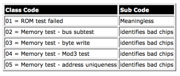
image.png

To identify the individual bad chips, we use this...
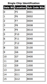
image.png

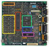
Unless I am in error, the 7A80 part would seem to indicate 6 bad chips at the following locations:

1000+2000+4000=7000, so: G9, G10 & G11

0800+0200=0A00, so: G6 & G8

0080 = F12
128K_MB.jpg

Strangely, Mouser doesn't have replacement chips but JAMECO does. As you can see on that page they are $2.25 each (+ shipping).  The JAMECO datasheet seems comparable to the datasheet of Apple's stock chips.

Any thoughts on what would 6 RAM chips to go bad?  Static discharge?


JDW

Well-known member
No replies after 24 hours indicates an "I don't know" scenario, so I decided to search the forum for an hour and found this 2016 comment by Uniserver.  It was his personal opinion that all the Apple logo RAM chips were just waiting to die and he didn't feel that selective replacement was a good idea, opting instead to replace them all.  Yet later in that thread I see one person who placed one chip successfully.  Whether that Mac is still running now in 2020 is unknown though.

It also isn't clear what the speed of the original 128K chips was.  Some people say 200ns and others 150ns.  The JAMECO RAM chips are mentioned as being 150ns, which indicates they must be the Siemens HYB 4164-2 chips mentioned in the datasheet they provide.  But if we compare the A.C. Characteristics on page 6-16 of that Siemens Datasheet to the same A.C Characteristics on page 1-4 of the Micron MT4264 datasheet, we see speed differences even between the 150ns chips...

image.png

(The Micron MT4264 (-15 or -20) were the stock chips used by Apple in the 128K motherboards.)

I am going to guess that the speed differences between the HYB 4164-2 & MT4264-15 are "within tolerance" of whatever the Apple 128K motherboard requires, but if anyone knows for a fact, please chime in.

(While it would seem prudent to just swap out all the stock RAM chips for JAMECO's 256x1 DRAM chips so as to get a 512K motherboard, such would also require the addition of a multiplexer.  Such is a non-trivial mod.)

My biggest problem at this point is that I do NOT have a Hot Air rework station.  I merely have a standard Desoldering Station.  Chip removal for multilayered motherboards like these are likely problematic at best for a regular desoldering station, and I would assume that a hot air station is really best to avoid problems on these RAM chips.  Have any of you been able to accomplish the job with a regular desoldering station?  (Soldering in new chips is easy.  I am talking about the desoldering and removal of the bad chips.)

Thanks.

 
Last edited by a moderator:

JDW

Well-known member
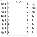
Thank you for your experienced input.  I certainly appreciate that.  That JAMECO web page you linked to is exactly the one I mention in my previous two posts.  That chip is show in the JAMECO/Siemens datasheet as this:

image.png

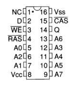
The above looks pin-compatible with the Micron MT4264 (which I linked in my previous 2 posts):

image.png

The pin-out markings look to be the same on both the JAMECO chip and the stock MT4264.  

Are you saying the MT4264 is not the stock chip?  Or are you saying the JAMECO chip physically will not fit into the holes due to the pin spacing being different?


LaPorta

Well-known member
The actual pin assignments do not seem to match up. Below is a diagram of the actual RAM chip socket pinout from the 128k/512k schematics that are available. As you can see, they do not match up. I looked a while for a solution, but I got too busy a month or so ago and never found one. Maybe we can find a solution now.

View attachment 35660


JDW

Well-known member
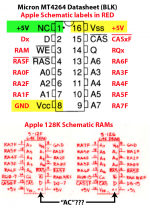
Let's start by considering this, noting the BLK & RED pin markings I've highlighted in YEL seem to conflict...

image.png

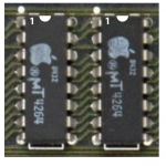
Pin markings on the JAMECO/Siemens Datasheet match the Micron data sheet, so we can be assured those two chips are the same and there are no labelling errors.  Those data sheets say Pin-1 is NC (not connected), so it shouldn't matter if there is +5V or GND connected to it.  The big problem is that if we believe the Apple Schematic to be 100% correct, that would mean Vdd and Vss are reversed, and if true, that would mean the JAMECO & Micron Chips would fry if mounted on a 128K motherboard.  Looking closely at an actual photo of a 128K motherboard, we see there are PCB traces leading from Pin-1 of each RAM chip...

image.png

If the Apple logo RAM chips were indeed the same as the JAMECO/Siemens and Micron RAM chips, why then would there be a trace connected to a pin the datasheet says is "NC"?  That would lead us to conclude that the Apple RAM chips must have been special.  But is that really so?  Not according to the evidence I just now uncovered.

On the page numbered "21" in the Dr. Dobbs Journal PDF, we find this...

image.png

That tells is the stock 128K RAM is rated at 200ns speed (which means any of the 150ns or faster chips should work perfectly fine), and that Dr. Dobbs article suggests using p/n 41256 when swapping out the 64Kx1 RAM chips in a 128K board to yield 512K of total RAM.  Looking up that 41256 part, we find this JAMECO 41256 datasheet which matches this secondary info I found searching the web...

41256, 41257
256Kx1 DRAM.
+----------+
A8 |1 +--+ 16| GND
D |2 15| /CAS
/WE |3 14| Q
/RAS |4 41256 13| A6
A0 |5 41257 12| A3
A2 |6 11| A4
A1 |7 10| A5
VCC |8 9| A7
+----------+


That 256Kx1 pinout gives strong evidence to show the 128K motherboard schematic is in ERROR with respect to the Vdd & Vss labels on the RAM chips.  As to why there is a trace coming from Pin-1, I can only conclude that because the 256Kx1 chips have A8 there, Apple must have wired something to it.  But as of the time of this writing, I have not used a continuity checker to see where that Pin-1 trace leads.

@LaPorta The question now is this.  Did you actually remove a stock RAM chip and solder in at least one of your JAMECO RAM chips into your 128K motherboard and test to determine your JAMECO chips do not work?  Or were you afraid by what you saw in the Apple schematic such that you never actually tested the JAMECO chips in your board?


LaPorta

Well-known member
I only discovered the discrepancy AFTER soldering in the chip, so I probably blew it. I have about ten more to try if we cook up another scheme. Let me know what I think we should try and I can. I do have a scope if need be.

To make this easier, here’s a link to my original thread:


JDW

Well-known member
I only discovered the discrepancy AFTER soldering in the chip, so I probably blew it. I have about ten more to try if we cook up another scheme. Let me know what I think we should try and I can. I do have a scope if need be.

To make this easier, here’s a link to my original thread:
I finished reading through your original thread and here are my thoughts...

1. As mentioned in my previous post, I strongly believe the Apple schematic to be in error with respect to the Vdd & Vss pins.  See that post for the evidence which I feel proves it.

2. In your original thread, @blusnowkitty clearly says he bought 4164 chips (i.e., the JAMECO/Siemens chips) and used them to fix his Mac.  That is further proof the Apple motherboard schematic MUST BE WRONG.

3. You said you spend "3 hours desoldering the 1 bad chip."  I'd like to know what you did for the removal to have taken that long.  (This is not criticism.  It is curiosity. I've never desoldered chips on those boards so I want to know.)

4. @bibilit said in your original thread that he uses 41256 chips (for 512K of RAM) without issue.  I mentioned those exact chips in my previous post.  He said nothing of Vdd & Vss being swapped.  That too proves, beyond any doubt, that the Apple schematic is wrong with regard to its Vss & Vdd markings.

5. It seems from your original thread that you added a new chip and powered the Mac on and got nothing.  You didn't say if you blew that chip.  It seems only that you ASSUMED you blew that new RAM chip.  It then seems you desoldered that new chip and replaced it with a second new chip, that second time lifting the legs of Vdd and Vss so as to reverse the voltage (based on your assumption the Apple schematic was correct).  You said that too didn't work, which doesn't surprise me since it's clear from all the evidence I've presented that the Apple schematic is incorrect.  So that second new chip was clearly fried by the reverse polarity.  Chances are if you test that first new chip, it would still work, and the fact your Mac failed to boot when you had that first new chip mounted indicates a problem other than that one bad RAM chip.

6. Just take a voltmeter and connect the BLK problem to a solid GND, and touch your RED probe on pin-16 of an existing Apple logo RAM chip with the power on.  You should see 0v or GND on the voltmeter because that pin, DESPITE what the Apple Schematic says, should be GND.  Then touch your RED probe to pin 8 on any of the Apple logo RAM chips and you should see +5V.  Maybe do that on a known-good motherboard first so you won't have doubts.  That will further prove the Apple schematic is wrong.  I cannot do this myself because I left all those Macs at the office and I am at home now and for the next couple days due to a holiday here in Japan.

I look forward to your reply.


LaPorta

Well-known member
It's been a while since I even worked on this so bear with me while I get my thoughts together.

Regarding the desoldering: the board I was working on had a heavy amount of oxidation (not corrosion) on all the pins and solder to the board. It took quite a lot of time, flux, and combination of regular iron and sucker desoldering iron to even free all the the pins up. Resoldering took no time at all due to not having to deal with that. There are 3 or 4 boards which needed repair probably 25 years ago that were part of some guy's repair shop and just never thrown out. Trust me, no though here of questioning my soldering skills. If I can learn a newer/better way of doing it, I am still a beginner with all this so I always appreciate help and tips.

The reason I was originally suspicious about the chips is that when I started up using that board originally, I got a chime, gray screen, and then the RAM test error with a sad Mac. After replacing the chip the first time, with no modification, I got no chime and no screen activity whatsoever...so it got me thinking that I must have messed something up with the RAM or the RAM itself was bad because going from RAM test showing a bad chip to NOTHING was concerning to me.

Another distinct possibility is that I somehow reversed the chip entirely. These chips have no notch or dot denoting the top or pin 1, so I went with a guess based on the orientation of the printed writing on it. If you know for certain what side has pin 1, please correct me.

I have one 512ke in my possession that works and has never been modified to my knowledge, so I can certainly use it as a test board to verify the +5v /0v to verify the pins in a working machine.

I still have probably 15 or so chips to use. I bought them to replace bad chips on all three boards. In this instance, I will use them to make sure that we all can figure out this mystery for certain (though I hope that does not take 15 good chips destroyed!).

My last thought was this: to make this a lot easier, I am just going to solder in mini sockets into the RAM chip spot. This way, we can test whatever we need and see what to do next without me taking forever to do it.


JDW

Well-known member
These chips have no notch or dot denoting the top or pin 1, so I went with a guess based on the orientation of the printed writing on it. If you know for certain what side has pin 1, please correct me.
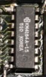
After reading through your other thread again, it seems you are referring to the JAMECO chips when you talk about "no notch or dot." I found this one photo in that thread:

image.png

It's very low resolution and blurry, but I can make out a round indentation in the upper left, which would indicate pin-1 is to its left, despite the fact there is another hole toward the bottom of the chip.  The oddball thing is, the JAMECO product page photos and the drawings of the chip on each of the data sheets linked on that page (NEC, Siemens, Samsung) show chips with a notch.  The KOREA printing and the logo shows the chips you have are SAMSUNG.  

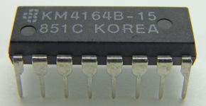
Here's a better photo I found on EBAY, which shows pin-1 at bottom-left:

image.png

You have the revision A chips, not B.  I would assume that the stock Apple chips would have been made about the time of those revision A Samsung chips, but I have no sources to prove that.  Sadly, I cannot for the life of me find a revision A datasheet.  That silly JAMECO product page links to the wrong SAMSUNG datasheet!  They link to the KM41464A which is a 64Kx4 chip, not the correct 64Kx1 chip needed on the 128K motherboard.  In fact, the NEC datasheet too is wrong, also being the 41464.  Only the Siemens datasheet is correct on that web page.  How confusing!  I wrote an email to JAMECO just now asking that they remove the 41464 data sheets from NEC and SAMSUNG and replace them with 4164 versions, especially the 4164A for the SAMSUNG, since it is Revision A that they apparently ship to customers.  I also came across this web page which, toward the end, talks about chip REFRESH differences between the A & B revisions.

I look forward to hearing the result of your voltage tests.


LaPorta

Well-known member
Thank you for that. I realized I made an error: I meant that I was unable to ascertain which of the dots indicated what pin (it was a few months ago).

 
Top