Mac SE ADB Controller

tony359

Well-known member
Can confirm the 87 and 88 both work - I have used a 88 in a SE and a 87 in a IIcx (using a little QFN to PLCC adapter board I made) both of which worked perfectly
Amazing thanks! I think my SE just needs a VIA but I will socket the ADB as well so I can test the programmed PIC as well.
Thanks for now!
 

Snial

Well-known member
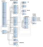
For my own interest I've done a bit of analysis on the flow control for the original PIC code. As per all PIC16C5x type MCUs, timing ends up using a lot of cycle counting, because there are no interrupts and the clock is too slow (2MHz => 500KIPs on these PICs) to use the TMR value accurately enough. Here's the flow diagram:

PicAdbExecutionPath.png

Undoubtably, it contains a few mistakes, but this gives you a feel for how it behaves. Function_002 dispatches to Function_052 to _060; Function_066 to _069 grabs AdbBytes and uses _029 to _051 to get each bit. Function_021 to _028 sends a byte (or bytes). Function_009 to _012 is VIA code and Function_013 to _015 fills memory.

Although the code involves a lot of cycle counting, nevertheless, bit timing isn't always exact. For example, if we look at _068 to _069, which gets an AdbByte:

function_068: ; address: 0x1d2 1d2: 9c5 call function_029[/FONT][/SIZE] [COLOR=rgb(65, 168, 95)][SIZE=3][FONT=courier new][B]1d3: bd4 goto function_069[/B][/FONT][/SIZE][/COLOR] [SIZE=3][FONT=courier new] function_069: ; address: 0x1d4 ; 1d4: 060 clrf INDF ; reg: 0x000 1d5: 9c5 call function_029 1d6: 120 iorwf INDF, F ; reg: 0x000 1d7: 360 rlf INDF, F ; reg: 0x000 1d8: 9c5 call function_029 1d9: 120 iorwf INDF, F ; reg: 0x000 1da: 360 rlf INDF, F ; reg: 0x000 1db: 9c5 call function_029 1dc: 120 iorwf INDF, F ; reg: 0x000 1dd: 360 rlf INDF, F ; reg: 0x000 1de: 9c5 call function_029 1df: 120 iorwf INDF, F ; reg: 0x000 1e0: 360 rlf INDF, F ; reg: 0x000 1e1: 9c5 call function_029 1e2: 120 iorwf INDF, F ; reg: 0x000 1e3: 360 rlf INDF, F ; reg: 0x000 1e4: 9c5 call function_029 1e5: 120 iorwf INDF, F ; reg: 0x000 1e6: 360 rlf INDF, F ; reg: 0x000 1e7: 9c5 call function_029 1e8: 120 iorwf INDF, F ; reg: 0x000 1e9: 360 rlf INDF, F ; reg: 0x000 1ea: 9c5 call function_029[/FONT][/SIZE] [COLOR=rgb(184, 49, 47)][SIZE=3][FONT=courier new][B]1eb: 120 iorwf INDF, F ; reg: 0x000 1ec: 3e4 incfsz FSR, F ; reg: 0x004 1ed: bd4 goto function_069[/B][/FONT][/SIZE][/COLOR] [SIZE=3][FONT=courier new]1ee: b37 goto function_050

The goto at 0x1db to the next line is a 2 cycle delay for timing purposes, but actually it adds 3 cycles including the clrf INDF. So, there's 3 cycles at the beginning of reading a byte. Yet there are only 2 cycles between each bit read. After reading a whole byte the code from 0x1eb to 0x1ed means there are 5 cycles between bytes (including the clrf INDF as before).

As it happens, I too have a Mac SE. However, it has a bust flyback transformer. I kinda want to interface my Mac SE to a VGA based LCD without having to use the flyback at all any more, but I also want to do it with a relatively simple MCU which generates VGA timings at CRT Macintosh frame rates at 1024 x 768 if that's possible. That is, each CRT scan from the SE is pixel-doubled to get 1024 pixels and similarly, the MCU would repeat that scan as well as adding a 21 scan margin at the top and bottom. If the MCU ends the Mac SE's frame at the bottom of the VGA scan, this would minimise how many scans need to be buffered at the top of the VGA frame (and a similar principle would work if a Mac SE's scan is faster than 2 VGA scan periods at 1024x768x60Hz). And I know there's a Raspberry PI + Expansion board CRT to VGA LCD converter, but these seems overkill to me, to use a computer a thousand x faster to convert a display for the SE.

Going back to the Adb PIC. What I'm thinking is that it might be useful to figure out a portable version, one that could work on an AVR or other MCU.
 

Tashtari

PIC Whisperer
Going back to the Adb PIC. What I'm thinking is that it might be useful to figure out a portable version, one that could work on an AVR or other MCU.
My code (well, it's not exactly mine, it's a butchered version of Apple's) runs on a PIC16F87 or 88 - what purposes are you thinking of that would justify a port to another microcontroller? Don't let me stop you if you're looking for a project, mind, I'm just curious.
 

Snial

Well-known member
My code (well, it's not exactly mine, it's a butchered version of Apple's) runs on a PIC16F87 or 88 - what purposes are you thinking of that would justify a port to another microcontroller? Don't let me stop you if you're looking for a project, mind, I'm just curious.
Ha - you might do well to discourage me from another pointless project! OK, why port it to another MCU?
1. I'd love to claim some high-minded principle, but I'm afraid some of my motivation is that I don't like PICs much ;-) !
2. Having said that, I think there's something to be gained from transcribing the algorithm in more abstract and cleaner terms. e.g. the PIC16F87 could probably implement a much cleaner version as it's a far superior MCU. Or e.g. in the original version the memory fill routines just store W in IND and keep incrementing FSR until it gets to 0. But that only works on the '54, because FSR is a 5-bit reg + bits 5..7 =111₂. So, incrementing FSR when it's set to 0x1111111 => 0, so it doesn't trample on any of the other SFRs in a different reg bank. Also, I've seen some specs which imply ADB timing isn't that critical, though it might be on a PIC with no interrupts (aaah, see later, timing is +/-3% for host, +/-30% for devices).
3. Digital preservation. I guess this project exists, because some of the PICs are now failing, or have been overloaded by live-plugging ADB devices? The future might not have PIC16F87's to hand (or a Mac enthusiast might not), so it'd be handy to use whatever's to hand, e.g. an Arduino with an adapter board.
4. Apple used different ADB MCUs from the start. The Apple ||gs used an M50740AL.
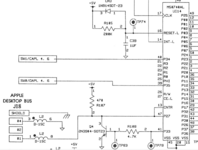
1673046395709.png

Which was a Mitsubishi 8-bit device a lot like a 6502, but not exactly the same!


You can see on the data sheet, section 3, about 15% down that the ADB pin is connected to P27 and CNTR - a counter reg? Given all the other functions the chip handles, it must use interrupts and so can't be 100% cycle compatible with the Mac SE's PIC version.

Finally, I found a couple of useful articles for the protocol itself:


But primarily, this is simply interesting to me, so I've no idea if I'd take it any further.

-cheers from Julz
 

demik

Well-known member
3. Digital preservation. I guess this project exists, because some of the PICs are now failing, or have been overloaded by live-plugging ADB devices? The future might not have PIC16F87's to hand (or a Mac enthusiast might not), so it'd be handy to use whatever's to hand, e.g. an Arduino with an adapter board.

More like battery bombed.

IIRC the ||gs ADB controller is closer to the Portable / early PowerBooks ones. It's suspected to be a M50740 as well.
 

Tashtari

PIC Whisperer
After remembering that the perfect is the enemy of the good-enough, I have released the current state of my annotation of the SE ADB controller firmware (along with the binary that is known to work).


Anyone willing to pick up the work of annotating the code where I left off is more than welcome to send me a PR. =)
 

Muirium

Member
This may be a hilariously naive question, so please forgive me in advance, but just how difficult would it be to install one of these into a Mac Plus to provide it with working ADB?

Obviously, I don’t even know what the “internal side” of this ADB controller speaks, or whether a Mac Plus has a logical place where it could hook up. Let alone whether Systems 6 and 7 had drivers for it, or even needed them. Very much a noob on this subject. You can tell that I am from the USB age. I’m used to making “converters” for my ADB, NeXT etc. keyboards for modern machines, which all just speak USB. These vintage Macs, meanwhile, are well beyond my knowledge.

Anyone knowledgeable and patient enough to describe just how wrong I am here, please feel free.
 

Arbee

Well-known member
The Plus' ROM lacks the ADB Manager and hardware drivers to speak to the SE's ADB modem (or this reproduction). The only practical solution would be something like a BMOW Wombat, except with keyboard/mouse connections for a Plus.
 

demik

Well-known member
The Plus' ROM lacks the ADB Manager and hardware drivers to speak to the SE's ADB modem (or this reproduction). The only practical solution would be something like a BMOW Wombat, except with keyboard/mouse connections for a Plus.

That's how it's done for ADB pointing devices with Quack. There is a lightweight ADB Manager inside than handle the mouse part. Obviously Quack lacks the keyboard part as it was not designed to provides keyboard services
 

tony359

Well-known member
I'm joining this conversation again to ask for an opinion.

Some time ago I made my own PIC using tashtari's code - my Mac SE started working again and happy days.
But over time that Macintosh was always unstable. Intermittently.

A few days ago I decided to play with the techstep I borrowed from max1zzz and discovered that the Macintosh was NOT passing the ADB test - but an identical Macintosh with an original ADB chip would pass it. And it's 100% the ADB chip: I swapped it between the two boards and now the board with the PIC fails the ADB test. Both ADB ports work fine.

"who cares". I notified tashtari, maybe it's just a quirk with the techstep.

However. Today I socketed both the SCC and the SCSI chips on the board which has the PIC. I tested the board after installing each socket, in case I broke something. Only after socketing the SCSI chip, I had an ADDRESS ERROR when loading the OS. Of course I blamed my work - until I realised that the Mac would boot fine WITHOUT a mouse connected!

1+1 = 3 so I put the original ADB chip back and: it works fine with a mouse.

And then I remembered: the other board also showed the same identical error when I went to test the BlueSCSI I built some time ago, with the PIC installed. But after insisting a bit it worked. This time I rebooted and power cycled many times and still didn't work but that's the very instability I've seen over time: the board fails to work for x minutes, then it works fine.

And now it seems that I have transferred this very instability to a different board by moving the PIC chip there. This is a whole different chassis (PSU and analogue board) so it's 100% caused by the PIC.

So my questions are:
- Am I the only one seeing these instabilities?
- Do I have a bad PIC? I think I read somewhere the TL866 isn't great at programming that chip. I have a T48 now - not sure if it would make a difference. Shall I re-program?

Ideas?
Thanks for the immense work in creating the ADB code! 👍
 

Tashtari

PIC Whisperer
That is hard to explain. I have to imagine it's something to do with the different clock speed of my port... maybe there's a change in the characteristics of the PIC's internal RC oscillator as it warms up that starts outside of spec and gradually moves into spec? That's just a guess, though. What this project really needs is a full reimplementation - my port is little more than a hack.
 

Arbee

Well-known member
I found a race condition in the original Apple code that the PIC was sometimes losing under emulation due to the different timing (time-slicing the emulated CPUs rather than trying to run them actually simultaneously). The upshot is that on the last bit of a byte being sent from the main CPU, sometimes the 68K got to changing the VIA ACR mode and tri-stating the line before the PIC had actually sampled the line's state.

Under emulation that mostly manifested as the mouse button appearing to be haunted and clicking itself, because ADB TALK commands to the mouse would sometimes go to the wrong device ID. It sounds like @tony359's problem is a bit weirder than that, although I'm not immediately sure how the ADB transceiver could cause those symptoms.
 

tony359

Well-known member
I've got some other PICs arriving, the 88 this time and not the 87. I'll test and report back!
 

tony359

Well-known member
Hi @Tashtari
Finally my PIC16F88 have arrived (after a seller sent me an empty bag because they wanted more money than advertised!).

Still the same issue.
The Mac boots but crashes almost immediately with an address error. The mouse either doesn't work or is not smooth - that is, it jumps around.
I believe that if I keep trying, eventually it would work but it's not a temperature issue, I tried warming up the board.

And I am 100% sure it's not my mainboard as the same issue happens with another one - though I haven't tried the 88 on that one and yes, there is a 1% chance that both boards have the same issue?

If I remember right, the system boots normally without ADB devices connected. I don't think I have another mouse to test to be honest but bear in mind that with a genuine ADB chip, everything works fine.

I'm a bit puzzled as right now the system is unusable - but clearly it's supposed to work? Any ideas? Anything I can do on my end to provide more data which might help?

Could it be my programmer? I've verified the chips and it never showed an error.

Thank you!
 

Tashtari

PIC Whisperer
I'm still thinking a quirk of the timing is the most likely cause... as before, there's very little else it could be. Looking at the configuration register bits for the PIC16F87/88, if the TL866/T48 somehow didn't program them (left them all set to 1), it seems like the PIC would never work at all. It may be worth it to check that the configuration register bits are set as defined at the top of the .asm file, but I doubt this is the problem. If it is the timing at fault, there's really very little that can be done about it, short of switching the PIC16F87/88 to use the crystal that drove the original PIC in a solution similar to the one described in this issue.

Update: thinking on this, there is one other possible remedy, though it's something of a long shot. PICs that use internal RC oscillators (as my code does in order to sort-of replicate the original PIC's execution speed) have a register called OSCTUNE that can be used to nudge the clock rate from its calibrated setting up to 12.5% in either direction. If this is set to -27 (100101) and my calculations (and the datasheet) are accurate, it should nudge the instruction clock from about 500 kHz down to about 447 kHz, closer matching that of the original PIC and hopefully eliminating timing as a potential cause of problems. Again, this is a long shot, but it's better than nothing - I've attached the hex file for you to try. Let me know if it does anything different.
 

Attachments

  • macseadb88-447.zip
    1.2 KB · Views: 0

tony359

Well-known member
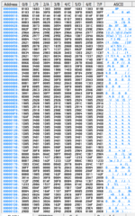
Silly question, @Tashtari, how does 0x2007 translates in what I see on the attached - or what Notepad++ in Hex mode displays?
 

Attachments

  • Screenshot 2025-04-15 225047.png
    Screenshot 2025-04-15 225047.png
    79.4 KB · Views: 8

Tashtari

PIC Whisperer
how does 0x2007 translates in what I see on the attached - or what Notepad++ in Hex mode displays?
Well, the configuration registers are outside the normal program memory space for the PIC, there's probably some special way of looking at them in your programmer's app. Not sure what it might be because I've never used the official app for the TL866+...
 
Top