Logic Board reworking: A Tale of Two IIcx

Addicted

Well-known member
I was lucky to land a non-working IIcx on the cheap. It looked better than it really was; the PSU would not stay on but would instead rapidly cycle on and off. After a basic recap, nothing improved. Lifting one of the chips in the PSU on/off support area (under the FDD/HDD caddy) revealed a lot of corrosion and grime. I replaced all the gates/diodes/transistors and, since they also looked corroded, the six bus latches between them and the ROMs (totaling nine SOICs and multiple SOT-23s) . I cleaned as I removed and new parts got nice bright pads and a grime-free area. This went really well, with only two (out of about 120) pads lifted; I was able to place solid, quality bodges to repair those.

That system now proceeds to boot if the load is low enough. Before the chip replacement, the PSU just would never stay on at all, and the ADB power key did nothing. Good news: the PSU logic replacement seems to have been correct; the power button on the rear of the IIcx as well as the soft-power on the ADB keyboard behave as expected. Bad news: Trying to boot with an HDD attached gets me back to cycling on/off, but that is unlikely the fault of the rework. Removing power from the HDD lets it proceed. Possibly +12V0 pulling down the whole system?

Progress! Now, step two: once the PSU locks 'on' (eg with no HDD), I get instant chimes of death, minor-chord-then-four-rising-chords.

OK, so I am about to pry open the PSU and try to improve its voltage regulation. I am not an electrical engineer. I know just enough to be unsure that a simple recap of the PSU will improve the regulation. I am wondering if I should look into replacing any semiconductors. I'll follow up on this topic when I get that far.

MEANWHILE...

I lucked into another cheap non-working IIcx. This one came with a working 1GB HDD, lots of DRAM, and a presumed-working genuine Apple 8*(2)4 video, so even if I cannot repair the system, I saved some nice things from the dump - at a bargain cost. DRAM Bank B held unmatched SIMMs (2x 4MB + 2x 1MB), so I took those out and just left Bank A with its 16MB of matching 4MB SIMMs.

It would boot with the video card and HDD powered, then go instantly to the same minor-chord-then-four-rising-chords. I left the PSU support logic and its caps alone, but replaced a few of the audio caps (I had spare tantalums on hand) and took a very close look around the battery. This unit also seems to have suffered some cap leakage underneath the FDD/HDD caddy: the bus multiplexers and the PSU logic chips all have very corroded leads and pads. I buffed them all with a soft toothbrush and a lot of 100% isopropyl alcohol, then 'flossed' between the leads with a fine-point wooden toothpick, ending with soaking the residues up with lint free lab tissues and ten minutes of air drying.

Voila, it regressed. Now its PSU will not stay on. So I probably turned some of the corrosion into slurry while cleaning up, pushed it under the chips, and now there are shorts. I have ordered another set of bus multiplexors and will lift, detail the board, and replace them.

WHY DID I POST ALL THIS BABBLE

Because now, I have two IIcx systems that have what seems to be the same problem. One also has a PSU that needs an overhaul, but both have the same Chimes of Death, immediately after power-on. So I came here to ask:

  • Any tips on proper rebuilds of sagging IIcx PSUs is welcome. I fear recapping is not necessarily enough. I've been watching YouTubes all evening.
  • Are there multiple chimes of death per system? Is the specific sequence of chords telling me something more than just "failed!" ? Is it a code, does "higher, higher, higher" mean (say) NuChip issues, versus Clock/PRAM fail, etc? Or does every IIcx always play the same chords no matter what has failed?
  • Any advice on what next to try? I will be cracking open the first IIcx's PSU and replacing everything I can identify, but all I know to do for the POST fail is to start examining both boards for broken traces and shorted pins, exhaustively. I do have the Gerbers and the Bomarc schematics, and a DVM.
  • Yes, my main hypothesis is that the six bus multiplexors (UH1-3, UJ1-3) are the problem. I may have not replaced them correctly in the first IIcx (soldering skills may not be up to that) + they have corroded or shorted joints and need replacement in the second one. But does the chime pattern say it's something else?
Thanks for reading. I hope to pay your time back by sharing useful experiences - after I succeed in debugging these two boxes.
 

nathall

Well-known member
I picked up a completely dead IIsi a while back to help restore my battery-bombed long-time workhorse IIsi.

The battery bombing of my IIsi happened around 8 years ago so it sat in storage since then. After dropping the re-capped logic from the dead donor into my IIsi, I was where you are at with the power cycling. It would boot from a floppy to the desktop if the HD was disconnected and there were no SIMMs in the RAM slots. Introduce either more RAM or the HD and it would power cycle.

Knowing this PSU used to work, I pulled it and recapped it; including that little daughter board with the two surface mounts. It now runs perfectly with 17MB of RAM, the 2GB Seagate and Radius NuBus video card like it did all those years ago. I did not replace any other components in the PSU. This was back in February. No issues since.

I don’t know anything about the IIcx PSU, but I’d try a simple recap and see where that gets you. :)
 

nathall

Well-known member
Now, to your other questions:

I have a IIfx on the bench with this death chime syndrome for the past two years now. Take a look at the Macintosh II section of the Dead Mac Scrolls. You will see different chord sequences mean different things. What yours means, I don’t know, because if I did, my IIfx would be working right now. It seems there are more “chime codes” than what is listed in the Dead Mac Scrolls.

At one point, I hooked my IIfx up to my Plus and was able to access the diagnostics mode via serial port. Apparently the commands and responses to this mode are unique to each model. I was able to execute some codes I found online in documentation for a base Macintosh II but the responses didn’t match anything I could find online and were as such, meaningless. (If someone has documentation for the IIfx or IIcx implementation of this, I’d be very grateful.)

YMMV.
 

Addicted

Well-known member
Excellent replies, thank you. BTW the Mac IIsi was the first Mac I owned. I loved that machine. I had the Apple FPU+NuBus adapter card. I forget whether my first NuBus card was a video card or the Pro Audio Spectrum 16. Probably the latter.

So, IIcx. I spent Saturday afternoon dismantling one of the IIcx power supplies. Not designed for serviceability. I have ordered new caps (electrolytics and safeties), new fans, and also the triac and main power transistors for both. I'll recap the first PSU and test it; if that doesn't do the trick, I'll replace the triac and FETs and try again.

I have overhauled fans before, but the one I am working with right now is really resisting removal of the blades from the spindle, so I just splurged for replacements.

I also printed an HDD caddy for the IIcx that did not come with an HDD, and built HDD activity-LED cables for both of them. I have printed programmer switches for both, but will repeat that b/c I chose a filament color that just isn't right, then tried black, which looked better than the empty gaps but I want 'authentic'. I ordered a more matching filament.

I have, contrary to my goals, increased the number of Macs I have here and now should perhaps use one as a host to attempt the remote diagnostics described in Inside Macintosh, or at least the ones not requiring the loopback board. Once I get the PSUs up, then the logic board issues will be next and diagnostics may be the way to go. I'll find the Scrolls and do some weekend reading, too.
 

nathall

Well-known member
Awesome. I’ll be checking here to see if you make any breakthroughs with the diagnostics mode. I’d REALLY like to get the IIfx working again.

The last year or so has seen me, like you, pick up more older Apples again. I spent quite a few years post-2003 culling the collection quite a bit, down from 40+ to single digits. I kept mostly just ones that had been with me since the 80s and 90s and special ones like the IIGS and IIfx.

Last year I added a workshop to the house, and now that I’ve got a dedicated bench I’ve hit double digits again. Gotta keep a lid on it this time.
 

Addicted

Well-known member
The PSU parts are due Wednesday (as in 31 Jul). As I plan the rebuild, I was wondering why one, not both of the large 470uF/200 working voltage caps is wrapped both in paper and again in heat shrink? Is this thermal protection? Static discharge protection? Vibration protection?
 

Addicted

Well-known member
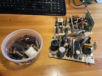
Finished one of the two IIcx PSU recappings. I chose the one for the IIcx that won't stay on, the one that click-click-clicks its relay instead.

Putting that PSU back in its IIcx, the system still just rapidly cycles when powered on. That's no surprise; I suspected corroded PSU logic on the main board before I started. I found the same problem on the other IIcx and fixed it by replacing the NANDs and FF. But it paid back my effort to have the recapped PSU pass its "smoke test". So my parts selection and procedures look OK.

Swapping this PSU into the IIcx that cannot stay on if the HDD is powered (if it is cabled to power) allowed that IIcx to stay on. So that seems to imply that the second IIcx's PSU is drooping, so I'll recap it tomorrow.

Is there a best place for me to upload the parts list for my work, for posterity? Would it help anyone else?

Tomorrow, I get my first dedicated, special-purpose, solder-rework hot air pencil. More like a candlepin bowling pin than a pencil, but.. need to find some expendable high-density boards to practice on before I scorch a Mac logic board by accident.

Humorous conclusion: a segment of high-diameter heat shrink tubing that's been cluttering up my toolbox for decades finally paid off! It was the perfect size for the added insulation on the rather large C8 (470µF 200WV), and I was left with just enough to do the other PSU. Hoarding can be a good thing.
 

Attachments

  • IMG_5250.jpeg
    IMG_5250.jpeg
    3.4 MB · Views: 27

Addicted

Well-known member
So, something appears to be pulling #PFW (power fail warning?) down, which would explain the PSU clicking problem that is my latest setback.

Oddly, if I plug a RasterOps Nubus card in, the PSU remains on, and PFW is not pulled down. Odder, if I plug either an Apple Nubus Video Card (630-0400) or an Asante Nubus card in, the PSU goes back to clicking and does not remain on.

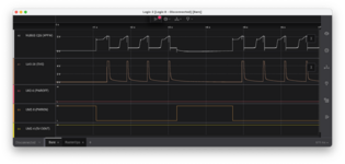
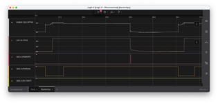
Scope traces attached. Names are <ChipLocation> - <pin>. Chip locations are from the silkscreen and agree with the Bomarc schematics.
  1. Channel A0 is the PFW, sampled at a Nubus connector, pin C23 (the label in the scope trace is wrong).
  2. Ch. A1 is the PSU's 5V output, sampled at a ROM.
  3. Ch. D2 is the power-off signal from the on-board logic, and it is acting as it should, pulsing when the PSU is up and the back power switch is pressed.
  4. Ch. D3 is the power-on signal (active low).
  5. Ch. D4 is the continuous 5V from the PSU.
In the "RasterOps" trace, things appear to be normal. Pressing the power button causes the PSU to power up. Once the PSU is up, pressing the power switch again (@ 4.05 sec) triggers a PSU shutdown by the on-board logic.

In the "No RasterOps" trace, #PFW drops ~55ms after the 5V rail rises (not implying casue and effect, however). The PSU shuts down accordingly. If the power switch or ADB button key remain down, it repeats this cycle. The continuous 5V from the PSU is steady, so it is not sagging and triggering a false shutdown. UK-2 and UM-2 do not seem to have any jitter that would trigger a state change. The lithium battery is fresh and reading 3.62V.

So.. I believe there is something else in the system pulling down #PFW. Or, it's another issue and I am only tracing the results of the real root cause. I have no explanation for why the RasterOp card masks the problem, since two other Nubus cards don't mask the problem.

Placing the RasterOps in any of the three Nubus slots masks the problem equally, so it's not a bad connector.

All three Nubus cards I have at my disposal are not yet known to work. (The IIcx I am trying to repair was going to be my Nubus test unit.) The RasterOps may be pulling up #PFW when it should not. I do not know. All three cards "look great", is all I can vouch for them.

Finally, this is with a recapped PSU. I have a second PSU, also recapped, that produces the same results on this logic board and Nubus configurations. There is certainly logic within the PSU that reacts to #PFW, and perhaps it is damaged in both PSUs. If the RasterOps is pulling on #PFW hard enough to counteract something lowering it inside the PSU, then, both the PSU and the RasterOps have faults. Not impossible. 30-year-old electronics.

Due to corrosion, I removed and replaced the PSU support logic on the logic board with new parts days ago. When this problem arose today, I probed their pins. The gates appear to be consistent, inputs versus outputs, at least on a single-sample basis.

I'm stumped.

(Edit: I have the 5V continuous line being sampled as a digital signal, which is incorrect. It should be sampled analog. While still somewhat useful, this will not reveal telltale sags. My bad. I will check it in analog tomorrow.)
 

Attachments

  • No RasterOps.png
    No RasterOps.png
    152.7 KB · Views: 13
  • RasterOps.png
    RasterOps.png
    148.6 KB · Views: 19
Last edited:

Arbee

Well-known member
Annoyingly I have the Apple schematics for the IIx and the IIci, but not the IIcx. And the IIci's power circuit is very different from the IIx's so I'm not sure if the IIcx is somewhere in the middle or what.

Assuming the IIcx is the same as the IIx, one suspicious thing is a thermal switch "TS1" between PFW and a 220 ohm pull-up resistor. Might be worth jumpering across that, since disconnecting the pull-up would presumably have the same effect as the board calling for power-down.
 

Addicted

Well-known member
I think I saw the thermal shutdown switch while recapping the PSUs. It's attached to the heat sink for the FETs, inside the supplies. I'll investigate it if I reopen either of them.
 
Last edited:

Addicted

Well-known member
After sleeping on it.. I have at least two problems, I think. The recapped PSU changed the behavior of the board. And the board may be tweaking the power fail trace, which may have always been the real reason the PSU seemed to need a recapping.

After recapping the second power supply, its logic board no longer reaches the Sad Chimes. Just silence. Perhaps several removals and insertions of the power supply flexed a connection on the board.

I'll probe the 68030 directly today to see if it being held in reset.

Or perhaps a previous repair - replacing capacitor-corroded address muxes - has come undone just coincidentally, and now ROM and RAM are inaccessible.

So this is a mess.

  1. I should re-recreate my scope setup from yesterday and be sure I am probing the signals I meant to probe.
  2. I am going to have to rig up an external ATX to remove one variable from the equation. I've looked for a compatible 2x5 pin connector Like the one on the logic board. I will look some more.
 

falecore

Member
I have a IIcx that would do the power cycle over and over. Cleaned the sh*t out of LB, recapped and put in a 7100 PSU and now all is well. I have another IIcx that was giving me death chimes on startup. I put in a Rominator II and pulled the y11(?) jumper and now it works great but crashes when I try to boot into ROM. Still trying to figure that one out.

Great that you were able to connect with some cheap IIcx's! Fun to work on and tend to be packed with goodies! I got one recently at the VCF swap with a Radius PrecisionColor Pro 24 in it!
 

Addicted

Well-known member
I've been distracted by an `040+CDROM+Ethernet Mac I literally found. It should be complete in a day or two, and become the workhorse Mac for restoring (and perhaps actually diagnosing) other Macs. I daydream about finding an internal SCSI CD-RW for it.

Then I plan to return to getting both of these IIcx systems running... got a serial cable to run the IIvx diags using the `040 as a debug host and everything.

The odds are looking dim, though: chimes of death on one, weird power-fail-warning mystery on the other, and no schematics...
 

Addicted

Well-known member
Summary: what resistance should be present between +5V and ground on a logic board with no ADBs, cards, RAM, or drives attached?

I worked on a IIcx with a recapped power supply that would not lock "on" after pressing either power button (keyboard or rear panel). The power supply relay starts clicking on-off until I release the button.

I recapped the logic board, including the large axials, and replaced the support logic for the power supply (chips @ UK2, UL2, UM2).

Checking my work with a continuity meter, things were great until I found on UM2 a set of pins that were weakly connected, the meter consistently showing 16.3 ohms resistance. The schematic showed two of the pins were inputs to an unused NAND and tied high for stability, but the other two were grounds.

So I am seeing 16.3 ohms across +5V and GND. On a logic board on a bench with no power supply attached.

I removed all the chips I had replaced and looked for solder bridges under them, and while they were out the resistance remained. I lifted one of my replacement capacitors to see if it might be bridging its pads, and it was not. I believe the other caps are OK, too.

Three of the six 74HC258s nearby were corroded, I lifted all six and the resistance remained. I put down new ones and called it a night.

The question is: do I have a short, or is that the usual resistance of the rest of the system across the five volt supply? I am afraid to power it up to test my repairs, now....
 

dougg3

Well-known member
A resistance of 16 ohms across +5V and GND on the logic board is normal. For example, here's another situation where a IIfx had similar results, and I have seen similar results on my IIci as well:


Addicted

Well-known member
Summary: great relevant thread; logic board not fried, PSU working; sad chimes; discussion of what the sad chime rule out.

Thanks for the swift reply, dougg3 ! The topic you mention is informative, and it also gave me some insight on the VGA adapter I use (the one mentioned in the thread). And I'll look at the IIcx schematics in case they share the inductor/fuse reversal mentioned in the thread..

I removed nine SOIC chips and the old caps with my first use of a desoldering air gun, and was worried that I might have damaged the substrate between inner planes on the logic board. I read the topic dougg3 mentioned and decided that was unlikely. I powered up my IIcx logic board. Sad chimes! Which is progress :) Because now, the PSU does stay on (and turns off when requested).

The chimes are instant on power-up.

Now.. what do Sad Chimes rule out? I'm going to list my guesses here. I'm up for education here.. trying to narrow my search for the source of the sad chimes.
  • I can infer that SWIM, AUDIO, and the audio DACs are happy.
    • Which implies address decode at GLU is working (SELSOUND and other signals are toggling). So, count GLU as happy, too.
  • The CPU and the ROM address space (ROMSEL) are functioning.
    • Chimes must be produced by ROM code and ROM data, because ROM SIMMs can bring their own chimes, right?
    • I can't rule out that an ASIC drives this, but it seems unlikely.
  • Yes, sad chimes must happen even without RAM, so, RAM errors are not ruled out.
  • The chimes sound clean, so the audio caps and the sound block's power ripple are within bounds.
  • No video, not even background, on the Apple Macintosh 8 Nubus, but I don't know if that card works yet, so, mm.
  • The speaker is not fried. (Obviously - but I was recently fooled in another effort by a cable I presumed could not be at fault.)
So the chime data is in ROM, GLU is working well enough to produce ROMSEL and SOUNDSEL, and the CPU needs no RAM to chime.

So, all I can guess from what I have is that sad chimes are due to fatal RAM access errors.

I'll double-check my soldering on those new 74F258s which I think manage SIMM interleaving. Will also inspect the PAL at UL15 and the inverters at UG7.

I'll try another set of SIMMs, too, or put these into an LC II and test them there.

I can check the resistor packs on the RAM address lines; if any have failed or are corroded, I have a few spares.

I am also back in position to use another Mac to host the IIcx diagnostics to gather some information on the sad chimes board - assuming the IIcx side works without RAM. Which would seem necessary.
 

Addicted

Well-known member
Summary: improved a few solder joints; still sad chimes; four flat tires verifying SIMMs; schematic errata found.

I reviewed this IIcx's RAM address bus.

I found a few newly soldered pins that were 1-3 ohms, a result of my getting tired late last night and not using enough paste - and my paste probably expiring about now. I tacked them down better. Will order fresh paste. Or just go back to the iron.

All of the muxes UH1 - UJ3 are solidly connected to their grounds, their supplies, their inputs, and the resistor packs at their outputs. No shorts exist between adjacent pins on those chips. Still, sad chimes.

I am assuming I did not overbake the new 74F258s while soldering them. That went pretty smoothly.

I took the SIMMs from the IIcx and tried to test them in another Mac. My LC I turns out to be parity-enabled (those exist, right?) and will not recognize any non-parity SIMMs. My LC II is sad chimes all of a sudden (long overdue for its logic board recap). The LC475/Q605 is 72-pin SIMM/DIMM. The Centris is 72-pin. Don't want to dismantle the SE just to verify a set of 1MB SIMMs. A workroom stacked high with Macs, but I still have no way to verify four 4MB 30-pin SIMMs.

Going through all those systems made a mess of my tiny workroom and things were in a spiral, so I did not attempt to use the LC I as a diagnostic host for the IIcx. Some other day. I am tired and bummed :(

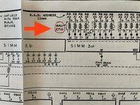
The one positive step forward I made today was finding a small typo on the Bomarc IIcx schematic. It's minor, it's probably already documented elsewhere on this site, but had me vexed for a few minutes until I 'got' it. Attached, for posterity.
 

Attachments

  • IMG_5264.jpg
    IMG_5264.jpg
    766.8 KB · Views: 13
Top