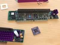
I did a CPU swap on the Pismo today and decided I did not really like the 7410 running at 2.0V. The 7410 I used is meant to be run at 1.8V in normal operation. If not overclocked it might even run stable at a little bit less.
I ripped the Pismo apart to check what kind of buck controller it is using and to change the core voltage on the logicboard if needed.
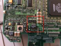
On the bottom of the board a MAX1636 can be found which is responsible for generating the 2.0V CPU core supply:
View attachment 21209
The MAX1636 has one feedback (FB) input for setting the output voltage. It can either be tied to ground or Vcc for fixed 3.3V or 2.5V output respectively.
By connecting FB to the output voltage through a resistor divider one can set the output voltage to any value.
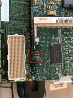
I traced where FB is going in the Pismo and luckily it is routed to the CPU daughtercard where resistor divider is located at R111, R112, R113 and R160:
View attachment 21210
The output voltage is calculated using the following formula:
Vout = Vref * ( 1 + R1 / R2 )
with Vref = 1.1V
R1 and R2 should be between 5k and 100k
On the Pismo CPU card R1 is formed by R160 and is populated with a 10k resistor.
R2 is formed out of R112 and R113 in parallel and R111 added to them in series. R111 is populated with 11k and R113 has a 0.576k resistor installed. R112 is left blank. R111 and R113 add up to 11.576k
To do the math this gives us 1.1V * ( 1 + 10k / 11.576k) = 2.05V
I took some resistors I harvested from old boards and put on 56k for R160 and 100k for R111. R113 is bridged with 0 ohms. Doing the maths should give me 1.716V.
CPU is running fine so far at 500MHz. I will be doing a few more tests to see if it is reliable and then might order correct resistors to go up to 1.8V if needed.


