David Cook
Well-known member
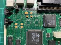
I recently bought two Macintosh IIsi computers. Neither worked upon arrival. The initial restoration steps are common:
1. Remove old battery
2. Blow out dust
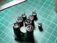
3. Replace the capacitors on the motherboard and power supply. I decided to replace the big capacitors on the power supply as well. They cost $3 each, but my labor is worth more. So, might as well complete the job in a single pass.
Next, I tested the power supply before reinstalling it in the computer.
4. Check for 5.1V (approximately) on pin 10. Hook meter ground to either pin 5, 6, or 7.
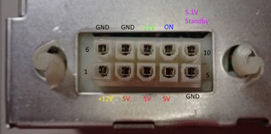
5. Using a low value resistor or a piece of wire, briefly connect pin 10 to pin 9. You should hear the relay click.
My relay did not click. There was no reason to try the power supply in the computer until this step works. I checked for blown fuses or other bad parts. I replaced some diodes and two bridge rectifiers, per other threads on this forum. All of the removed parts tested as working -- so they were not the problem.
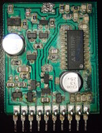
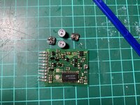
Let's take a look at how the vertical PWM switching boards looked in each of my power supplies before replacing the capacitors. Gross!
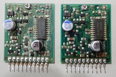
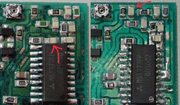
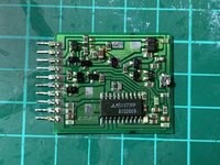
Replacing the capacitors and ultrasonic cleaning the boards removed the cause of the destruction, but not all the damage. Inspecting the chip pins with magnification revealed why the power supply was not turning on.
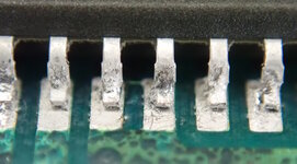
From above, without magnification, I could not tell that the solder had been eaten away by capacitor leakage and that many of the pins (and leads on other components) were either disconnected or intermittently connected. I carefully picked away, cleaned, and resoldered every dull joint on the vertical board. Afterwards, the power supply clicked its relay when pins 9 and 10 were contacted!
You won't be able to test the other power supply voltages until it is attached to the motherboard or other load, because the power supply turns off instantly.
Upon connecting each power supply to a motherboard, I was greeted with one Mac with sad chimes and one Mac that wouldn't power on at all.
My mistake was not inspecting the motherboard for dull joints, flaky solder, or floating pins, as I had found on the power supply PWM board. Pay particular attention to all parts near the old capacitors.
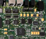
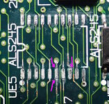
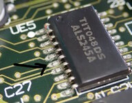
The source of the Sad Mac chimes were floating pins on UE5. This prevented proper access to onboard memory, causing the ROM startup test to fail. Honestly, these pins didn't look bad to naked eyes after the board was ultrasonically cleaned. But, tapping them with a dental pick showed they were completely loose. In other people's photographs I see leakage on UE5. So, you should always check here.
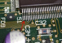
Here's another dull solder joint. Is that leg of Q5 actually electrically connected? Or has the chemistry/bond of the damaged solder been altered? I don't know, but it needed to be addressed by picking, cleaning, and resoldering. By the way, notice this part is near a replaced capacitor.
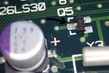
This fixed the Sad Mac IIsi!
The other Mac IIsi doesn't respond to the rear power button or the keyboard power button. Here is the chip that monitors the power buttons. You can test it without the power supply by simply making sure you have a fresh PRAM battery installed.
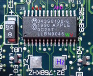
Pin 14: GND
Pin 13 (V): +V around 3 volts supplied by the battery.
Pin 25 (B): Should be around 3 volts, but drops to 0 when the rear button is pressed.
Pin 24 (K): Should be around 3 volts, but drops to 0 when the keyboard power button is pressed.
You can also check pin 2 (reset) for 3 volts to make sure the 68HC05 isn't being held in reset.
Assuming all of this checks out, test the pad labeled Hz in the above image. See below where an oscilloscope is connected to battery ground and the lower pad for the crystal.
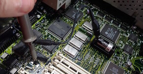
Even with only a battery installed, you should see a nice waveform on this pad. If you don't have an oscilloscope, a good multimeter should be able to display a frequency of 32768 Hz (32.768 kHz). This is the 68HC05 clock. If the waveform isn't present, then the chip can't run, and thus can't turn on the power.
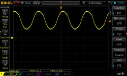
On the dead IIsi, there was no waveform! Replacing the crystal fixed the problem and the board powered up and ran nicely.
Hopefully my experiences will help you next time you're restoring a IIsi or other classic Mac. Basically, assume every dull joint is broken.
- David
1. Remove old battery
2. Blow out dust
3. Replace the capacitors on the motherboard and power supply. I decided to replace the big capacitors on the power supply as well. They cost $3 each, but my labor is worth more. So, might as well complete the job in a single pass.
Next, I tested the power supply before reinstalling it in the computer.
4. Check for 5.1V (approximately) on pin 10. Hook meter ground to either pin 5, 6, or 7.

5. Using a low value resistor or a piece of wire, briefly connect pin 10 to pin 9. You should hear the relay click.
My relay did not click. There was no reason to try the power supply in the computer until this step works. I checked for blown fuses or other bad parts. I replaced some diodes and two bridge rectifiers, per other threads on this forum. All of the removed parts tested as working -- so they were not the problem.
Let's take a look at how the vertical PWM switching boards looked in each of my power supplies before replacing the capacitors. Gross!

Replacing the capacitors and ultrasonic cleaning the boards removed the cause of the destruction, but not all the damage. Inspecting the chip pins with magnification revealed why the power supply was not turning on.

From above, without magnification, I could not tell that the solder had been eaten away by capacitor leakage and that many of the pins (and leads on other components) were either disconnected or intermittently connected. I carefully picked away, cleaned, and resoldered every dull joint on the vertical board. Afterwards, the power supply clicked its relay when pins 9 and 10 were contacted!
You won't be able to test the other power supply voltages until it is attached to the motherboard or other load, because the power supply turns off instantly.
Upon connecting each power supply to a motherboard, I was greeted with one Mac with sad chimes and one Mac that wouldn't power on at all.
My mistake was not inspecting the motherboard for dull joints, flaky solder, or floating pins, as I had found on the power supply PWM board. Pay particular attention to all parts near the old capacitors.
The source of the Sad Mac chimes were floating pins on UE5. This prevented proper access to onboard memory, causing the ROM startup test to fail. Honestly, these pins didn't look bad to naked eyes after the board was ultrasonically cleaned. But, tapping them with a dental pick showed they were completely loose. In other people's photographs I see leakage on UE5. So, you should always check here.

Here's another dull solder joint. Is that leg of Q5 actually electrically connected? Or has the chemistry/bond of the damaged solder been altered? I don't know, but it needed to be addressed by picking, cleaning, and resoldering. By the way, notice this part is near a replaced capacitor.

This fixed the Sad Mac IIsi!
The other Mac IIsi doesn't respond to the rear power button or the keyboard power button. Here is the chip that monitors the power buttons. You can test it without the power supply by simply making sure you have a fresh PRAM battery installed.

Pin 14: GND
Pin 13 (V): +V around 3 volts supplied by the battery.
Pin 25 (B): Should be around 3 volts, but drops to 0 when the rear button is pressed.
Pin 24 (K): Should be around 3 volts, but drops to 0 when the keyboard power button is pressed.
You can also check pin 2 (reset) for 3 volts to make sure the 68HC05 isn't being held in reset.
Assuming all of this checks out, test the pad labeled Hz in the above image. See below where an oscilloscope is connected to battery ground and the lower pad for the crystal.

Even with only a battery installed, you should see a nice waveform on this pad. If you don't have an oscilloscope, a good multimeter should be able to display a frequency of 32768 Hz (32.768 kHz). This is the 68HC05 clock. If the waveform isn't present, then the chip can't run, and thus can't turn on the power.

On the dead IIsi, there was no waveform! Replacing the crystal fixed the problem and the board powered up and ran nicely.
Hopefully my experiences will help you next time you're restoring a IIsi or other classic Mac. Basically, assume every dull joint is broken.
- David

