You are using an out of date browser. It may not display this or other websites correctly.
You should upgrade or use an alternative browser.
You should upgrade or use an alternative browser.
Getting G3 Whisper Perch USB working
- Thread starter croissantking
- Start date
croissantking
Well-known member
Some context:
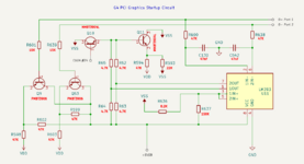
With the Mac shut down, but plugged in and supplying +5V standby
- 5V 10mA is supplied to the D- lines at USB ports 1 and 2 through the transistors at Q9 and Q53.
- A resistor divider connected to 1IN+ and 2IN+ sets Vref (the reference voltage – in this case, 0.26V) for the LM393 comparator to use as a baseline.
- 0.65V is supplied at 1IN- and 2IN-, which is above Vref and therefore the comparator is inactive.
- 1OUT and 2OUT are close to 0V.
When someone presses the keyboard power key
– The power key connects one of the D- lines to ground.
- Depending on which USB port the keyboard is connected to, the voltage at the corresponding comparator input drops to 0V, below Vref.
- One side of the comparator becomes active and puts out 2.5V at the corresponding output.
- The whole circuit – and most importantly the pair of transistors at Q10 and Q11 – becomes active. Pin 24 of the CUDA chip is pulled low through Q10, signalling the Mac to turn on.
Daniël
Well-known member
Page 16 of the Gossamer DVT schematic details the soft power circuitry, if you want to verify things with that.
croissantking
Well-known member
This is great, I didn’t know about these schematics. I thought you were about to show me that all my reverse engineering work was unnecessary but these are just for the logic board itself.Page 16 of the Gossamer DVT schematic details the soft power circuitry, if you want to verify things with that.
CooI to see the PERCH Connector pinout and confirm that the USB startup circuitry I’ve worked on interfaces with kbdSwitch and Trickle5V.
Some other interesting details in there too, such as ‘CLONE power supply support’ next to the schematics for the Mac/ATX supply jumper, and the sword and globus cruciger illustration (Gossamer’s Story…?). Also, we can see which pull-up and pull-down resistors connect to GRKLPLL0 and GRKLPLL1 which would allow us to set 100MHz bus operation.
Last edited:
zefrenchtoon
Well-known member
what can we say about these schematics ...? ^^'This is great, I didn’t know about these schematics. I thought you were about to show me that all my reverse engineering work was unnecessary but these are just for the logic board itself.
CooI to see the PERCH Connector pinout and confirm that the USB startup circuitry I’ve worked on interfaces with kbdSwitch and Trickle5V.
Some other interesting details in there too, such as ‘CLONE power supply support’ next to the schematics for the Mac/ATX supply jumper, and the sword and globus cruciger illustration (Gossamer’s Story…?). Also, we can see which pull-up and pull-down resistors connect to GRKLPLL0 and GRKLPLL1 which would allow us to set 100MHz bus operation.
G3 B&W schematics
Hi crews, did anyone ever see the schematics for the Power Macintosh G3 B&W aka Yosemite? I was able to spot schematics for some Power Macintoshes on this forum. There is a page out here that offers schematics for PM G3 Beige and some G4 Macs as well. Unfortunately, no schematics for Yosemite...
 68kmla.org
croissantking
Well-known member
Haha!what can we say about these schematics ...? ^^'
G3 B&W schematics
Hi crews, did anyone ever see the schematics for the Power Macintosh G3 B&W aka Yosemite? I was able to spot schematics for some Power Macintoshes on this forum. There is a page out here that offers schematics for PM G3 Beige and some G4 Macs as well. Unfortunately, no schematics for Yosemite...68kmla.org
Well, yes, it would have been convenient to have access to this before.
I find it interesting to see how Apple laid out the circuit diagram for the power-on circuit compared to how I’ve done it.
It seems there are optional diodes that can be stuffed for 'hysteresis', I wonder what effect that would have.
Last edited:
Not sure if anyone noticed, but in another thread was linked this manual (PDF) which contained this picture:
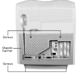
A few other pages show this card from behind and you can clearly see the USB connectors populated from the other side too.
This only seems to be in the AIO manual, though. I can't see it in the Desktop/MT ones.

A few other pages show this card from behind and you can clearly see the USB connectors populated from the other side too.
This only seems to be in the AIO manual, though. I can't see it in the Desktop/MT ones.
croissantking
Well-known member
Nice find, very interesting.
croissantking
Well-known member
Is that a photo, or a digital drawing? Interesting that they show two ports in a horizontal orientation (in relation to the Personality Card PCB).
You are right.
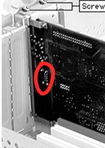
The footprint is different than the production Whisper V2 card – it has a dual port, horizontal USB header, rather than a single port, vertical header – there must be another prototype floating around, maybe in one of these AIOs (but perhaps now long since destroyed?).
other pages show this card from behind and you can clearly see the USB connectors populated
You are right.

The footprint is different than the production Whisper V2 card – it has a dual port, horizontal USB header, rather than a single port, vertical header – there must be another prototype floating around, maybe in one of these AIOs (but perhaps now long since destroyed?).
Last edited:
croissantking
Well-known member
croissantking
Well-known member
DarthNvader
Well-known member
@LightBulbFun if you may want to know how to get your XPC106 to 100MHz operation.Also, we can see which pull-up and pull-down resistors connect to GRKLPLL0 and GRKLPLL1 which would allow us to set 100MHz bus operation.
@croissantking Did you ever get USB to work here?
croissantking
Well-known member
Yeah it fully works. See my write up and schematics@croissantking Did you ever get USB to work here?
DarthNvader
Well-known member
Thanks, great, @LightBulbFun put a 100MHz XPC106 on one of his Beige boards, I've been searching for one of those chips because I don't want to pull one form a working B&W or Yikes LoBo.Yeah it fully works. See my write up and schematics
I've got a shop that should be able to do the swap for me if we can ever get @LightBulbFun to confirm 100Mhz bus operation on the Beige???
I'll pass along your schematics to my tech and see if he can do that mod too.
@joevt So now I am wondering if there is a version of the Beige G3 ROM we don't have, like a version 3v+ with USB OHCI support in the ROM.
DarthNvader
Well-known member
I've got an untested assumed to be working G4 Yikes LoBo, I don't want to get too far off topic, but will it operate without the front panel board?
Will this USB circuit power on the LoBo from a USB KB without the need for the Front Panel board connected?
croissantking
Well-known member
Yeah I’m looking for an XPC106/100 as well, think Durosity may be sending me one at some point. I’m planning to do the BGA rework myself, and I’d get a hot plate for this. Very interested to know if it works. Or if someone else can confirm, then I don’t have toThanks, great, @LightBulbFun put a 100MHz XPC106 on one of his Beige boards, I've been searching for one of those chips because I don't want to pull one form a working B&W or Yikes LoBo.
I offer to do the mod in case you’re interested.I'll pass along your schematics to my tech and see if he can do that mod too.
See this thread. I got hold of the 77D.45F3 ROM that was the subject of the discussion. It’s essentially an unreleased Rev D but sadly does not have any built in USB support. That doesn’t mean there isn’t another prototype ROM out there which does, of course.@joevt So now I am wondering if there is a version of the Beige G3 ROM we don't have, like a version 3v+ with USB OHCI support in the ROM.
I've got an untested assumed to be working G4 Yikes LoBo, I don't want to get too far off topic, but will it operate without the front panel board?
Will this USB circuit power on the LoBo from a USB KB without the need for the Front Panel board connected?
Uh, yeah, I’d imagine so. I’d guess the front panel button pulls the startup pin on the CUDA chip low, the same as the keyboard does.
Last edited:
Trekintosh
Well-known member
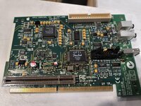
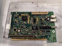
Far from my finest work but it'll do I think. I forgot the 10k bridge resistor because I'm using the firelink IC, but I'll get that on before I test it.
Peep how well the ultrasonic cleaner did on the flux removal. The trick is to use extremely toxic MG 4010A flux remover in a beefy ziplock, put the board in that, then put the bag in the ultrasonic cleaner with distilled water. Works a treat.
Please excuse the gigantic images. My new phone is a bit overloaded on megapixels.
Attachments
Trekintosh
Well-known member
Of course a Wings card comes up on eBay immediately after posting this. I chucked an offer at it, so maybe this was just my practice board :v
I got a few extras of all the parts, I bet I can cobble together the rest from my stocks.
Edit: sorry for double posting. The forum I use most has auto merging if you do two posts within an hour.
I got a few extras of all the parts, I bet I can cobble together the rest from my stocks.
Edit: sorry for double posting. The forum I use most has auto merging if you do two posts within an hour.
Sorry for being pedantic, but it looks like MG 4010A is mostly ethanol, D5, and isopropyl alcohol. I still wouldn't do shots of it, but you probably could, so extremely toxic is an exaggeration. Extremely volatile, perhaps. Disclaimer: I am not a doctor, and this does not constitute medical advice. If you choose to drink flux remover, the consequences of doing so are your sole responsibility.The trick is to use extremely toxic MG 4010A flux remover...
Now back to our regularly-scheduled programming.
Trekintosh
Well-known member
How about extremely stinky?Sorry for being pedantic, but it looks like MG 4010A is mostly ethanol, D5, and isopropyl alcohol. I still wouldn't do shots of it, but you probably could, so extremely toxic is an exaggeration. Extremely volatile, perhaps. Disclaimer: I am not a doctor, and this does not constitute medical advice. If you choose to drink flux remover, the consequences of doing so are your sole responsibility.
Now back to our regularly-scheduled programming.
Also yeah I got that wings card. If anyone wants this whisper card after i confirm it's working Im happy to sell it on.
Similar threads
- Replies
- 19
- Views
- 1K
- Replies
- 4
- Views
- 570
- Replies
- 6
- Views
- 1K
- Replies
- 9
- Views
- 637
- Replies
- 4
- Views
- 1K

