• Updated 2023-07-12: Hello, Guest! Welcome back, and be sure to check out this follow-up post about our outage a week or so ago.

Getting G3 Whisper Perch USB working

croissantking

Well-known member
I've been silently following this thread ever since the beginning and very much enjoyed it! Really nice work!

Glad you’ve enjoyed, and nice to have a decent following on this project.

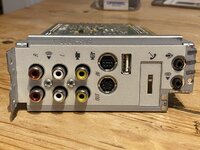
I somehow just today discovered that for the past decade, I've had a Beige G3 Desktop that came from the factory with a DVD drive, and indeed it has a Bordeaux card inside. With the knowledge that I actually have one here in front of me and I also have a multimeter and know how to use it, is there anything I can do on my end to help complete your notes so we have a BOM for adding the USB ports to Bordeaux cards?

Haha, that’s awesome. I didn’t know any Desktop models came with the DVD option, but there you go.

Sure, you can compare its layout to the Whisper card schematics that are on GitHub and note down the labels for each component, which will all be different (I assume just based on the fact that the Wings card component labels are all different from the Whisper). The basic layout should be similar except that it will have some additional complexity due to supporting 2x USB ports. I have no idea what kind of dual USB port header would fit the odd footprint - I did look but came up with nothing.

The Whisper and Wings layouts are 98% the same, just with totally different numbering.

Is it rare enough that it would be a sin to modify it? :D
No, not at all. Do it. You’ll have the only Bordeaux card in the world with USB.

P.S. I’ve drawn up the schematics for the Wings card if you’d like to see it. In fact I’ll upload it to GitHub tomorrow.
 
Last edited:

dougg3

Well-known member
I have uploaded the latest schematics for Wings and Whisper to the GitHub repository: https://github.com/CroissantKing/G3-Personality-Card-USB.

I worked out the values for both the optional Unitrode power supply section and keyboard power on section, but they are as yet untested.

Very, very cool! It'll be fun to hear how the testing goes with the keyboard power on.

I have no idea what kind of dual USB port header would fit the odd footprint - I did look but came up with nothing.

Ahh, I didn't factor that into it. Very good point. I also haven't had any luck finding anything even close. It's interesting that the footprint on the PCB has two square pads (usually used for denoting pin 1). I wonder what is up with that. It sure would be fun to look through a 1998 version of a TE/AMP or Amphenol USB connectors catalog to see if they have anything weird like this mystery connector.

No, not at all. Do it. You’ll have the only Bordeaux card in the world with USB.

I'd definitely be interested, but only if I can somehow find the correct USB port assembly to put into it. I'm also not 100% sure that I trust myself to cut out the holes without making a mess of it!
 

croissantking

Well-known member
Very, very cool! It'll be fun to hear how the testing goes with the keyboard power on.
I’ve ordered the components needed from Mouser and they’re on the way, so I’ll have an update if I’m successful in a couple of days.

Ahh, I didn't factor that into it. Very good point. I also haven't had any luck finding anything even close. It's interesting that the footprint on the PCB has two square pads (usually used for denoting pin 1). I wonder what is up with that. It sure would be fun to look through a 1998 version of a TE/AMP or Amphenol USB connectors catalog to see if they have anything weird like this mystery connector.

It’s weird, right?

I'd definitely be interested, but only if I can somehow find the correct USB port assembly to put into it. I'm also not 100% sure that I trust myself to cut out the holes without making a mess of it!

Yeah you need to know what you’re doing as it’s thick metal and quite hard to cut. I’m getting better at it but it’s still a pain to do.

IMG_9359.jpeg

IMG_9364.jpeg

The good thing is that the backplate is the same as the one used on the Wings card so not super rare at least.

Edit: also, examine the backside of your card, I believe a lot of the empty footprint is there, same as the Wings A/V. On the Whisper all components are on the front and it’s easier to work on.
 

croissantking

Well-known member
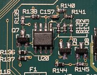
I populated one of my Whisper cards as attached, but I could not get it to work properly. Now, with the card installed, the Mac starts up as soon as the power lead is plugged in. If I switch it off with the front panel button, it just starts up again.

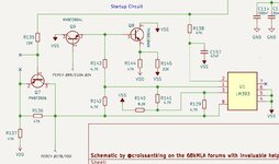
I think the issue will be in the R139/R140/R141 area, as this is the part on the G4 I looked at that differed and I had to make some guesses as to the values of the components. I now want to look at a Bondi Blue iMac logic board and see if it can give me any more clues.

Can anyone tell me what the function of this circuit is? I know it’s for the keyboard startup function, but what’s the comparator for etc? Just curious.
 

Attachments

  • IMG_9422.jpeg
    IMG_9422.jpeg
    162.4 KB · Views: 19
  • IMG_9421.jpeg
    IMG_9421.jpeg
    649 KB · Views: 22
Last edited:

croissantking

Well-known member
I've been studying the circuit in detail and reading up about comparators and voltage dividers, and now understand the principle better. I measured the voltages on the comparator on my G4 and fed them into ChatGPT along with my schematic. It has given me some new values to try for the unknown resistors which provide the reference voltage.

R141: 4.7kΩ (as before)
R139: 470Ω
 
Last edited:

croissantking

Well-known member
ChatGPT values were correct?! That’s awesome!
It picked the right values for the voltage divider but got the two resistors the wrong way around. It's definitely not perfect, but it helped me push this over the line 100%.

So I now have a Beige G3 with a USB keyboard that starts up the machine when the power key is pressed.

I wonder how much that prototype is worth now...
 
Last edited:

croissantking

Well-known member
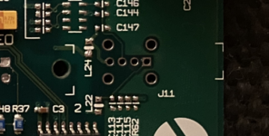
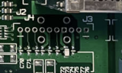
@dougg3 I've just been looking at the footprint of the Bordeaux card again.

See how it is marked both as J3 and J4, I am actually thinking that one of those options is just to use the same single port that I've been using on the other cards. The middle of the footprint is the same distance away from the backplate so it would likely work.

Then... did Apple create another option to fit a pin header and a breakout board where dual USB ports could be panel mounted? It would explain why there are extra holes, as a couple of them could be doubling up for the shield. In fact I can see that the last two are right on the ground plane.

So either of the square pads is Pin 1 depending on which header you choose to fit. Dual USB ports would better, and it would save you having to cut into your backplate, but where would you mount them? Maybe in the opening of the modem port – in a way that's detachable so that you could fit a modem if you wanted?

Screenshot 2024-07-25 at 00.54.34.png
Screenshot 2024-07-25 at 00.53.43.png
 
Last edited:

dougg3

Well-known member
So I now have a Beige G3 with a USB keyboard that starts up the machine when the power key is pressed.

I wonder how much that prototype is worth now...

Yay! Excellent job! What a fun use for ChatGPT. I wonder how similar that circuit is on the G3 Blue and White. I have a couple of those motherboards laying around and might be able to check.

See how it is marked both as J3 and J4, I am actually thinking that one of those options is just to use the same single port that I've been using on the other cards. The middle of the footprint is the same distance away from the backplate so it would likely work.

I think you're onto something! That all checks out -- it never occurred to me that if you start from that inner square pad, it appears to be exactly correct in terms of pinout and positioning for the single port assembly. That totally explains the two square pads.

10 pins never really made any sense for directly mounting a dual USB socket anyway. I would have expected 8.

I actually asked The Connector People if they had any USB catalogs from that era around 1997-ish and Dave responded saying he is not aware of any connectors that have two USB ports stacked in that orientation. The closest he found was FCI 73725-0110B which is just a single port and looks like it probably matches the 4-pin port you've been using.

Then... did Apple create another option to fit a pin header and a breakout board where dual USB ports could be panel mounted? It would explain why there are extra holes, as a couple of them could be doubling up for the shield. In fact I can see that the last two are right on the ground plane.

So either of the square pads is Pin 1 depending on which header you choose to fit. Dual USB ports would better, and it would save you having to cut into your backplate, but where would you mount them? Maybe in the opening of the modem port – in a way that's detachable so that you could fit a modem if you wanted?

Yeah, that makes complete sense! Based on what you said earlier, and after more self-reflection, I would be crazy to attempt cutting any holes myself (although it's good to know the backplate is identical to less rare cards!). Doing something with that modem port opening seems like a much more accessible (not to mention clever) idea. I guess another potential option is a simple custom PCB that mounts vertically on the 10-pin header and then has two normal flat USB-A ports on it, but it feels like that would be flimsy since there wouldn't be any support to hold it in place. It would need a way of attaching at the top. And it would require cutting holes. I'm thinking I don't want to cut any holes. Your modem opening idea is brilliant!


It's kind of funny that C77 is populated on the card all by itself. I wonder if they forgot to mark it as do not place...or maybe if it's a decoupling cap it still serves a small purpose for other nearby components or something.
 

croissantking

Well-known member
Yay! Excellent job! What a fun use for ChatGPT.

Definitely! It’s very cool that when I uploaded the schematic it knew it was a startup circuit — it’s a standard layout, apparently. I learned a lot from its explanations.

I wonder how similar that circuit is on the G3 Blue and White. I have a couple of those motherboards laying around and might be able to check.

I studied the one from the G4 Yikes - the B/W should be the same, or similar?

I think you're onto something! That all checks out -- it never occurred to me that if you start from that inner square pad, it appears to be exactly correct in terms of pinout and positioning for the single port assembly. That totally explains the two square pads.

Thank you for confirming my suspicions :)

Yeah, that makes complete sense! Based on what you said earlier, and after more self-reflection, I would be crazy to attempt cutting any holes myself (although it's good to know the backplate is identical to less rare cards!). Doing something with that modem port opening seems like a much more accessible (not to mention clever) idea. I guess another potential option is a simple custom PCB that mounts vertically on the 10-pin header and then has two normal flat USB-A ports on it, but it feels like that would be flimsy since there wouldn't be any support to hold it in place. It would need a way of attaching at the top. And it would require cutting holes. I'm thinking I don't want to cut any holes. Your modem opening idea is brilliant!

I really like your idea of a custom PCB. One possible way to secure it would be with a screw mount similar to how it’s done on the adjacent RCA assembly.

For the modem port opening, something will have to be designed so that it fits securely in place. Do you have any ideas?

It's kind of funny that C77 is populated on the card all by itself. I wonder if they forgot to mark it as do not place...or maybe if it's a decoupling cap it still serves a small purpose for other nearby components or something.

I noticed that too, it’s amusing. Wonder what the value on that is too, to see if it’s the same as the value I originally chose for that part.
 
Last edited:

dougg3

Well-known member

So cool!

I studied the one from the G4 Yikes - the B/W should be the same, or similar?

Ahh, you're right. I probably wouldn't be adding any new info. I knew that...I just wasn't thinking!

For the modem port opening, something will have to be designed so that it fits securely in place. Do you have any ideas?

I haven't paid close attention to how that opening works, but the next time I have the card out I'll think about it a bit. This sounds kind of crazy, but I guess someone could make a PCB in the same shape as the modem and just plug it into the modem slot purely for mechanical strength or something. I'm not sure how to make the metal plate though.

I noticed that too, it’s amusing. Wonder what the value on that is too, to see if it’s the same as the value I originally chose for that part.

I can desolder it and measure it with my multimeter sometime. Looks like it's probably the equivalent of C113 on Whisper and and C256 on Wings. Interestingly it seems to be a larger part than the equivalent capacitor on Whisper at least.
 

croissantking

Well-known member
Ahh, you're right. I probably wouldn't be adding any new info. I knew that...I just wasn't thinking!

Don't let me put you off. I noticed quite a few unstuffed pads near R636, so it would be interesting to see if the actual configuration is different. What I'd expect to be the the same is the PCB layout.

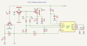
On the G4 Yikes [as compared to the Beige G3] the reference voltage of 0.26V going into 1IN+ is generated differently, and there is an additional connection from 2OUT. It seems odd to me, on the G4, that 2OUT is part of the circuit when 2IN- and 2IN+ are both n/c. LM393 is a dual comparator but only one half of it is apparently used.


5f906a75-be1e-4988-ac96-ea2146007998.JPG

I haven't paid close attention to how that opening works, but the next time I have the card out I'll think about it a bit. This sounds kind of crazy, but I guess someone could make a PCB in the same shape as the modem and just plug it into the modem slot purely for mechanical strength or something. I'm not sure how to make the metal plate though.

How about a 3D printed housing, like a little box, for a small PCB with dual USB header onboard? The housing could have clips on two (or maybe four) sides where it meets the modem opening, 'clicking' into place from behind. It could have a couple of legs that extend down to touch the Personality card's PCB for extra mechanical stability when inserting a USB device.

This could also be adapted for your idea of a longer PCB that fits into the modem slot. In that case you could replicate the design of the modem's metal plate on the 3D print, having a tab on the top edge only. You would latch the card into the opening and then hinge it down into the modem slot. It would be like a dummy modem card with a dual USB header and space for other stuff [but not quite sure what!] :)
 
Last edited:

croissantking

Well-known member
I have now updated the GitHub repository with brand new BOMs for the Wings card, which includes the fully working startup circuit. I've also added links to Mouser projects in the readme, so it should be hassle free to mod your own card!
 

obsolete

Well-known member
Love this! Really looking forward to trying it out on my G3 AIO when I pull it out of the closet one of these days. Thank you for sharing and documenting all your great work.
 

croissantking

Well-known member
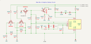
Here's the iMac G3 Rev. A USB keyboard startup circuit. It's just like the Beige G3 except that it uses both sides of the comparator as it has dual USB ports. I'd expect the Bordeaux card to do something similar, @dougg3 .

I must take a look at the G4 PCI Graphics layout again, as I've labelled 2IN- and 2IN+ as being not connected, but as it also has dual ports (and 2OUT is wired up) they must be connected to something...

Screenshot 2024-08-03 at 23.51.28.png

Thanks for the iMac board, @mg.man , it's been an obedient test subject so far.
 

dougg3

Well-known member
Here's the iMac G3 Rev. A USB keyboard startup circuit. It's just like the Beige G3 except that it uses both sides of the comparator as it has dual USB ports. I'd expect the Bordeaux card to do something similar, @dougg3 .

Nice! Thanks, that's very helpful! I will definitely take a look when I have a chance.

How about a 3D printed housing, like a little box, for a small PCB with dual USB header onboard? The housing could have clips on two (or maybe four) sides where it meets the modem opening, 'clicking' into place from behind.

I love this idea too! Realistically I'm not sure when I'll have time to play around with it, but I suppose for starters I could just wire up a couple of ports to a header. I'm guessing having the port shield touching the chassis ground is important though, since you mentioned way back in this thread how the reliability improved after you had the backplate in place.

This could also be adapted for your idea of a longer PCB that fits into the modem slot.
It would be like a dummy modem card with a dual USB header and space for other stuff [but not quite sure what!] :)

Yes! That would be an interesting idea too.
 

croissantking

Well-known member
I'm guessing having the port shield touching the chassis ground is important though, since you mentioned way back in this thread how the reliability improved after you had the backplate in place.
That’s pretty good attention to detail. Yes, I did have issues with sudden restarts and the volume going up and down when I sometimes plugged in a device. It went away after I fitted the backplate and I never saw the issue again.

I’ll be happy to design a 3D printable solution for the USB header if you get as far as populating your card.
 
Top