Durosity
Well-known member
Yes, fully recapped now.Did you say the PSU was recapped?
I'm gonna try and make a video of this.What is it actually doing when the analog board is connected? Which rails are dropping down?
That's a good idea.. I never really thought about the ceramic caps or diodes. I've already taken pics that I'm gonna be sending to @3lectr1cPPC for their MacDAT database (along with a whole load of other stuff).. I've also documented every electrolytic cap in the PSU, Analogue Board, and Neckboard along with their measurements, so people know what replacements to buy.My knowledge isn’t advanced either but perhaps you could start by using a multimeter in continuity mode to check any ceramic caps and diodes for shorts. Place the leads across each component in turn and see if it beeps (it shouldn’t).
Maybe map out the analog board beforehand by taking a photo, printing it out and marking off each component you’ve tested as you go along.
Yeah done that, although I may go over it and do it again to be sure I didn't miss any!Is it worth reflowing all the joints as another starting point if not done already?
Sorry, my knowledge is limited here too, but its always good to rule out the easy things.
To an extent.. mental energy for it has dipped!Perseverance is the main key.
Yeah.. I mean.. I learned a fair bit about this back In electronics class at school.. but that was in 1993.. It's something I've always wanted to learn more about and frankly I have actually learned a great deal so far whilst doing all this, so that is at least a nice silver lining!analog boards and power supplies are hell to work on (at least from my perspective, as a bit of an electronics noob), unless you are really accustomed to how they actually work and have some of that core electrical engineering skillset - I attended electronics class at school but I wouldn't say I remember a lot of it, and I've never properly sat down and spent the time to learn the skill in a serious way.
Yeah.. I actually contacted LG to see if they happened to have anything, the agent I spoke to said they get quite a few requests for that kind of older information, but alas it's not something they have access to (and he's not even sure if it still exists). I fully believe that all electronic equipment should be required to come with a full schematic by law.Also, having no schematic available doesn't help matters at all...
Oh my yes. I'm being super super careful!things can get spicy...I know everyone knows this, but please stay safe when doing the poking.
Yeah it's a brand new flyback, although to be fair I have no way to know that it isn't also defective. However that was useful info, I knew that FBTs failed, but I didn't know why so that's actually quite illuminating!From what I've been reading, that's also why the flybacks fail, apparently the lower quality LG made flybacks when overheating, will cook the lacquer off the windings, which then causes the internal arcing which presents itself as unpleasant "zapping", which causes the image to distort as it zaps.
If the internal shorts are bad enough, that can cause the situation to become worse, to the point that the machine won't power on at all, shutting off the second the flyback receives power and immediately shorts itself out.
That's the case for iMac G3s, but also the Molar Mac, which has a strongly related CRT chassis from what I understand.
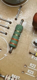
This is where I would start from, maybe seeing what other stuff is connected to R726.
Yeah I might move back to that, see what it finds
Well brand new but it's impossible to say if its not also defective.. though seems unlikely 2 would have failed in exactly the same way.Did you use a known good flyback?
Alas yeah.. that's the problem. I'm pretty certain that someone who's experienced in CRT repair woulda worked this out in 5 mins.. but alas there's so few of them around these days.. If only I had a Time Machine..That does make this a more difficult to solve issue, I fear.


