• Updated 2023-07-12: Hello, Guest! Welcome back, and be sure to check out this follow-up post about our outage a week or so ago.

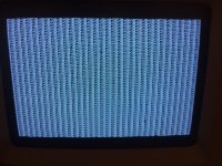
Extra confusing Classic checkerboard

jyeandle

Member
I recently acquired a Classic, which boot and ran when arrived, although the sound didn't work. Cracked the case and was pleased that someone had removed the battery long ago and there was zero battery damage, but I noticed that there was some slight cap leakage around C8 and C9, although it was very slight. I removed all the old caps, gave the board a good thorough washing, and recapped with tantalum caps. However, owing to it being my first experience with tantalum caps, I had assumed the stripe was negative, since every other kind of polarized cap I've dealt with stripes the negative end. The result was I soldered them all on backwards. Didn't realize it until I powered the machine up and C8 exploded. Removed all those caps and threw them away. Thankfully I had bought a bunch of them to have on hand. Put new one's in oriented correctly, and powered up the machine to a checkerboard screen.

Brought out the multimeter and checked traces around the caps for damage and continuity. They all checked out okay. Checked the voltage; 5.03 and 12.09, so that's right where it needs to be.

Started probing signals at various points on the board just to see what was working and what wasn't. And I discovered that the CPU reset line is being held low (it's low enabled), so the CPU is stuck in a reset loop. To test a theory, I jumpered 5v to the CPU reset pin, and it booted up to the flashing disk icon (I did this test with all the drives disconnected). It also gave me the startup bong, which it hadn't done before I recapped, so yay for working sound. But, when I remove the jumper wire the display freezes until power is cycled and it goes back to checkerboard.

So I traced the reset line for continuity. It checks out. Then I poked around the reset button circuit. All the traces and components check out. The reset button circuit is connected to a pin on the sound IC (UA5), which is next to the pin the CPU reset line connects. I don't know pin numbers, and have been unable to find a datasheet on that chip. But if you're standing the board up so the writing is horizontal, it's on the bottom of the chip on the right hand side. Checking the voltage at that point reads 5v with the reset button unpressed, which is what I expected. But pressing the reset button drops that to 3.48v, not the logic low that I expected. Pressed or unpressed, the CPU reset line stays at ground.

So, I'm hoping this is a situation others have experienced before. My theories so far are:

Theory 1: I damaged the sound IC when I put the caps on backwards. Though, if I have damaged it, the fact that I got sound when I jumpered the reset line seems more puzzling. But, it's possible I suppose that somehow the CPU reset line is shorted to ground internal to the chip. Though, it still remains a puzzle why pressing the reset button only drops from 5v to 3.48 at the sound IC.

Theory 2: The reset line is shorted to ground internal to one of the other ICs that it connects to (it connects to half the ICs on the board).

Theory 3: The CPU reset line is shorted to ground at a trace or via, and after hours of searching I still haven't been able to spot it.

Theory 4: Ground isn't ground on the logic board. For ease, when probing I was using the hard drive power connector ground under the assumption that it would be the same ground as the logic board.

Anywhere else I can check? Worst case scenario I can just permanently jumper the CPU reset line to 5v. But, that means I can only restart the computer by power cycling, and although that's not a huge deal, if I can fix it so that it's working properly that is the ideal scenario.

 

Alex

Well-known member
I sort of understand the issue, sort of because I don't know how to properly measure the voltages so I don't even know what they should be but check this article (link below), you might have seen it already but it does go through resets and voltages. You should quickly come to determine if the article is helpful or not.

https://archive.org/stream/Classic_Mac_Repair_Notes/Classic_Mac_Repair_Notes_djvu.txt

From what I have read, I wonder if the power supply is actually delivering the proper voltage and is not dipping enough to cause the checkerboard, I believe this can happen, at least this is how I understood things from the first link I sent you.

In terms of what I suspect is the "343S0045-B" UA5 Sound IC, I too haven't been able to find a data sheet but I wonder if the Guide_to_the_Macintosh_Family_Hardware (Second Edition).pdf that is on archive.org has more for you on this front. Also, I was thinking, the MAME (MESS) emulator people probably know a thing or two about that chip, especially because they had to emulate it. I wonder if they might have a data sheet or some other reference. Incidentally I found a link, http://mess.redump.net/mess/driver_info/mac_technical_notes but it might not be enough. I really wish I could help you further but I hope the @techknight chimes in because he has quite a bit of knowledge and he may know.

I will be watching this with interest.

Best wishes.

 
Last edited by a moderator:

Bolle

Well-known member
On most Macs the CPU reset line is controlled by the sound IC.

Some models use the DAC to check if the clock signal (and maybe the 5V supply) are stable and once that's the case the chip will get the whole system out of reset.

Default state is that the CPU reset is held low by the sound IC. There should be a pullup resistor somewhere on the CPU reset line. See if you can find that and check if it actually works.

I would not recommend jumpering the reset line right to 5V as you might send a lot of current through wherever it is tied to ground.

EDIT: Not totally sure and don't have my Classic at hand right now to check but it looks like there is one of the Sony soundchips on there. Those can go bad (or weak) resulting in glitchy reset behaviour.

I think Larry Pina described that you can add a second pullup resistor somewhere in the 1k-10k range right to the sound IC to get around the issue while maintaining a working reset switch.

 
Last edited by a moderator:

jyeandle

Member
I think Larry Pina described that you can add a second pullup resistor somewhere in the 1k-10k range right to the sound IC to get around the issue while maintaining a working reset switch.


Any idea what the source was? I quickly skimmed a few of his books that I could find in pdf online and and saw nothing about sounds ICs in any of them.


techknight

Well-known member
Sound IC UA5 is potentially damaged. However:

The reset button pulls to ground a 47ohm by 47ohm (R93/R96) resistor divider from 5V. So it should pull it down to 2.5V and not 3.48 so there could be circuit issues there. But again I cant count for any voltage output from the sound IC that would disturb your typical R/2R resistor latter formulas. So you need to check your connections there. 

Also Pin 6 is the reset drive output, and its pulled up to 5V via a 1K resistor at R73 so check that. make sure its still connected to each of its nodes. 1 end of it is at 5V potential and should ring out anywhere there is 5V, and same thing with the other end to RESET output. otherwise the line will float. 

Worse comes to worse you can pull the UA5 sound IC and check for cap goo underneath. 

 
Last edited by a moderator:

jyeandle

Member
Sound IC UA5 is potentially damaged. However:

The reset button pulls to ground a 47ohm by 47ohm (R93/R96) resistor divider from 5V. So it should pull it down to 2.5V and not 3.48 so there could be circuit issues there. But again I cant count for any voltage output from the sound IC that would disturb your typical R/2R resistor latter formulas. So you need to check your connections there. 

Also Pin 6 is the reset drive output, and its pulled up to 5V via a 1K resistor at R73 so check that. make sure its still connected to each of its nodes. 1 end of it is at 5V potential and should ring out anywhere there is 5V, and same thing with the other end to RESET output. otherwise the line will float. 

Worse comes to worse you can pull the UA5 sound IC and check for cap goo underneath. 


Any elegant way to pull up UA5? I havent quite worked my soldering chops up to the level of cleanly removing surface mount ICs, and I don't have access to any reflow equipment. It's not seated flush to the board, so I was able to floss around an alcohol wipe underneath to some extent through the gaps in the pins around the corners. If it can be done, I have no objections to pulling it up to clean, but I don't want to risk destroying it in the process.

R73 is measuring 0.98k on the board. The right side of the resistor is at 5V, the left is reading 91.6mV. 

R93 is measuring in at 45.6ohms and R96 at 48 even. With the reset button not pressed, both sides of R93 and R96 are reading 5v. With the reset button pressed, R93 reads 5v on the left, 3.84 on the right, and R96 reads 3.48 on the left and 1.72 on the right. Tracing that further back, when it crosses through the bourne filter it drops to 0.74mV when the reset button is pressed. So my guess is the bourne filter is responsible for the asymmetry in the voltage divider, and why the 5v isn't being cleanly cut in half to 2.5.

Checking between logic board ground (board disconnected) at the molex connector and pin 6 of the sound IC has a resistance of 1.26k, likewise checking +5v at the molex connector and pin 6 yields 0.98k (not a surprise, given that's how it measured across R73, but was worth double checking). The fact that pin 6 to ground has a resistance means it's not shorted to ground, correct? So something is pulling it low? Shame I cant think of an easy way to just disconnect pin 6 and test the voltage levels on the line then... Though, I do have small enough nippers that I could clip the pins at the halfway point, and just solder bridge them if the pulling down is happening elsewhere. I'll give that some thought after I've had a good nights rest.


jyeandle

Member
Got tired of trying to figure it out. Cut pin 6 on the sound IC. Boots right up. Everything works except the reset button on the side. Even selecting restart from the special menu works. Also, sound still works.

Only thing not working at this point is the floppy drive. I have two drives, and neither of them worked. But, new problems for a new day. For now I'll just be content with the fact that it once again boots.

41990539_10217518425332956_9088933968442556416_n.jpg


jyeandle

Member
Scratch that... Back to not working. While trying to diagnose the lack of working floppy, I was probing signals at the floppy connector to verify voltages. They were reading funky, as in -7.4, -10.2, etc. Then I started smelling what smelled like a cap shorting out, the screen froze, and upon power cycle, new video fun...


unnamed (1).jpg


jyeandle

Member
Bleh. I know what happened... I flipped the connector in my head, put the negative probe of the multimeter on +12 rather than ground, and the positive probe on 5v... Hence why the multimeter gave me a reading of -7. And why I smelled a chip dying... Hopefully I haven't killed the entire board. :-/  I do have a spare logic board that was a victim of battery explosion, which someone removed the BBU from. And the 68000 on it, along with the VIA, RTC, and sound IC, are all corroded and probably unusable. But, I can harvest the RAM, SWIM, SCSI, and SCC and swap those onto the now formerly working board if needed...

Not sure where to start with this one though... At this point, might be more practical just to try to find a new logic board..


jyeandle

Member
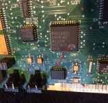
Have you got  picture of the pin 6 on the sound chip ?

Thanks.
Its not the clearest of pictures, sorry. Drew an arrow pointing to pin 6. Although it's hard to tell from this angle, it is cut. There's no contact between the pin and the board.

unnamed (3).jpg


jyeandle

Member
Hmmm... Upon plugging it back in and turning it on today, I'm back to a checkerboard. Only, this time it's not being caused by the CPU reset line...

Anyone know of where I can get a new logic board without having to buy (and ship) a whole new classic off ebay? Working would be preferred, but even if it doesn't, at this point I'm not above chip swapping until I have a working board.


techknight

Well-known member
UA5 was definitely bad. 

However when using the multimeter the way you did would NOT have done any damage at all unless your probes were set in Current (ma/A) mode instead of volts/ohms mode. 

the burning smell was likely something giving up the ghost,

a guess scenario would be you slipped on your probe when trying to read stuff and went oops, I shorted something out, Better not mention that mistake on the forum. Or, you did it unwittingly and cant recall it. Either way, anything like this will fry an IC faster than a fart flies in a fan factory. I have done that so many times I cant count.  

Either that, or your sniffer is just smelling "old". But in my experience, I tend to believe the above is what happened. And if it happened in the connector you were probing, you killed the SWIM, this will prevent a boot. 

The RESET line has to be toggled low, and then high during power-on otherwise the CPU can get into an indeterminate state, and youll get these errors. 

Also have you recapped the analog board/power supply? if not we are all wasting our time! It is a known issue, and voltages have to be stable before any true assessments can be made. Like leaving 10 year old fuel in your car while trying to service your engine for a misfire. 

 
Last edited by a moderator:

jyeandle

Member
UA5 was definitely bad. 

However when using the multimeter the way you did would NOT have done any damage at all unless your probes were set in Current (ma/A) mode instead of volts/ohms mode. 

the burning smell was likely something giving up the ghost,

a guess scenario would be you slipped on your probe when trying to read stuff and went oops, I shorted something out, Better not mention that mistake on the forum. Or, you did it unwittingly and cant recall it. Either way, anything like this will fry an IC faster than a fart flies in a fan factory. I have done that so many times I cant count.  

Either that, or your sniffer is just smelling "old". But in my experience, I tend to believe the above is what happened. And if it happened in the connector you were probing, you killed the SWIM, this will prevent a boot. 

The RESET line has to be toggled low, and then high during power-on otherwise the CPU can get into an indeterminate state, and youll get these errors. 

Also have you recapped the analog board/power supply? if not we are all wasting our time! It is a known issue, and voltages have to be stable before any true assessments can be made. Like leaving 10 year old fuel in your car while trying to service your engine for a misfire. 


As I said a few posts above, retracing what I had done I realized after the fact that I brainfarted and connected one probe to +12 and the other to a logic pin, likely one of the phase lines, though I'm not sure which one. So, I'm figuring most likely the swim is dead as a result. And hoping it's ONLY the swim is dead as a result. I do have one I can swap over, though I'm waiting on some chipquik to arrive tomorrow to do that.

So is UA5 responsible for toggling the line low/high? I know it does when the reset button is pressed, but does it also do that on power up? It had been working fine with the pin clipped until I went and shorted out the swim.

Where could I find a new UA5? The only source I could think of would be from another logic board. But I'm assuming any logic board that has a UA5 in good enough condition to be a suitable donor would be in good enough condition that I could just use the whole board and not futz around with swapping chips. Was that chip/form factor used in any other mac? Google has not been my friend when it comes to that...

The AB hasn't been recapped, yet. They've been ordered, so that'll happen when they arrive. But I don't see/smell any evidence that they've started leaking yet. I don't have a scope, so I dont know how much ripple is in the power coming off the AB, but the voltages are within spec, and I would assume C5, C6, C8, C9, C44, C45, C51 and C55 on the LB offer some ripple filtering...


techknight

Well-known member
the IC contains the brown-out detector for the 5V supply. so when the 5V becomes stable, the sound IC releases the RESET line. that is how it works. 

Finding another one wouldnt be easy. 

However, you can do a little bit of hackery and substitute in another control IC for the RESET line. 

There is a 3 pin IC that would work good for that. 1 pin would be gnd, other would be 5V, and the 3rd would be reset line. But you would need to re-rig the circuit so the reset button still worked as well, or it wont work. 

An easier method would simply be cutting the trace at the reset button, and wire the reset button directly to the reset line. 

So if it powers up as a checkerboard or something else, you can tap reset which will pull the RESET line to ground and release it. That would work as well. 

 
Last edited by a moderator:

jyeandle

Member
I actually kind of like the idea of using an IC that's meant to deal with this problem. Poked around and stumbled across the datasheet for the MAX809JTRG. It's a 3 pin IC like you mentioned, with a 4v trigger threshold. So I could connected its Vin as is to pin 7 on the sound IC, which is normally at 5v and drops to 3.84 when the button is pressed, which is below the threshold for it to pulse the reset output, which I can connect to the RESET line. Should work, unless I'm completely wrong about how the IC operates.

Didn't get a chance to swap the SWIM chip out today, or deal with the machine at all. Projects for tomorrow... 

 
Top