• Updated 2023-07-12: Hello, Guest! Welcome back, and be sure to check out this follow-up post about our outage a week or so ago.

Mac Classic video problem

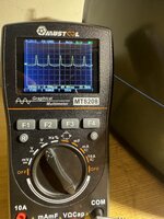
Hello to everyone, after recapped my Mac Classic (Analogic Board and Logic Board), everything was working really good but after 10 minutes i got an Horizontal line (picture1)
Before this thing happend, i heared a strange and little noise came from analogic board like a buzz but i didn't gave importance (i thought was normal) but after 10 minutes i got an Horizontal line (picture 1).
I started to chech what it could be and i found that on PIN 16 (power supply) of my TEA2037 i didn't have the 9.8V necessary to let start the vertical section.
I checked for a bad cap or transistor and i discovered tha the cap CF2 was gone (it's near the power of TEA2037).
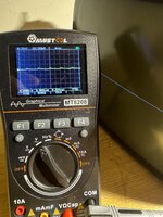
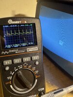
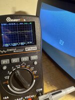
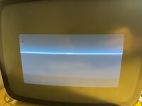
After change it, the Vertical IC start to work but now i have this situation showed in the picture 2.
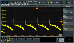
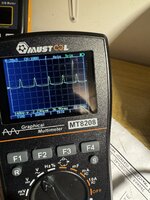
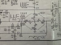
I checked everything (caps and resistor) and i controlled also the wave by oscilloscope on BD1 (YOKE PLUG) and i have this result:
PIN 1 : 22.5Khz wave (good)
PIN 2 : ground
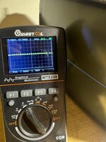
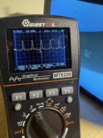
PIN 3 : on this i don't have as showed in the sheet instruction the right frequency (i got 3/5 hz pulsing instead of 60.15 Hz stable) - picture 3
PIN 4 : 60.15 Hz wave (good)
I tried to change the TEA2037 but nothing, always the same result....
So i just ask for some HELP because i don't know what it could be.
 

Attachments

  • 1.jpg
    1.jpg
    875.7 KB · Views: 36
  • 2.jpg
    2.jpg
    557.8 KB · Views: 28
  • IMG_6102.jpeg
    IMG_6102.jpeg
    1.7 MB · Views: 27
Last edited:
However, i tested my logic board with anouther mac classic AB and it work perfectly.. so it’s a problem of this Analogical Board and i would like to repair it
 
Hello, sorry for delay, i just make same pictures from my osciloscope of my Analogic Board (with my Logical board connected that i tested that work perfectly).
These are signal that i got from the BD1 plug
starting from pin1 to pin 4.
As showed on pin1 i have 22.25Khz, nothing on pin 2 (ground) but nothing on pin 3 and pin 4 where i expected to see the 60.15 hz signals (with differet wave). I tested the TIA (on anouther Analogic Board) and it’s good..
 

Attachments

  • IMG_6158.jpeg
    IMG_6158.jpeg
    1.6 MB · Views: 12
  • IMG_6159.jpeg
    IMG_6159.jpeg
    1.5 MB · Views: 10
  • IMG_6160.jpeg
    IMG_6160.jpeg
    1.3 MB · Views: 11
  • IMG_6161.jpeg
    IMG_6161.jpeg
    1.4 MB · Views: 16

bpetersen

Active member
Since your last post, I managed to get an oscilloscope to debug my problem (similar but on the horizontal). I at first had trouble getting the 60Hz traces too, but I realized I just wasn't triggering on them. Adjusting my scope, I got the one on pin 4 fine. The signal on pin 3 is the same height, so then I could get that too, but it was never stable -- the period varied enough that it was jumpy. At any rate, given that my vertical deflection seems ok, I'd say that's ok.

Here is what my pin 4 on the yoke looks like (attached). Granted, mine may not be ideal or correct either (would love feedback from others), but it looks roughly like the drawing in the schematic. I do worry that it isn't smooth though. My horizontal looks way worse (not smooth at all).
 

Attachments

  • v-sync yoke.png
    v-sync yoke.png
    107.4 KB · Views: 12
Since your last post, I managed to get an oscilloscope to debug my problem (similar but on the horizontal). I at first had trouble getting the 60Hz traces too, but I realized I just wasn't triggering on them. Adjusting my scope, I got the one on pin 4 fine. The signal on pin 3 is the same height, so then I could get that too, but it was never stable -- the period varied enough that it was jumpy. At any rate, given that my vertical deflection seems ok, I'd say that's ok.

Here is what my pin 4 on the yoke looks like (attached). Granted, mine may not be ideal or correct either (would love feedback from others), but it looks roughly like the drawing in the schematic. I do worry that it isn't smooth though. My horizontal looks way worse (not smooth at all).
Hello, this is what i get from pin4 on a good Analogical board that i use the check the difference:
If i see yours is like mine
 

Attachments

  • IMG_6157.jpeg
    IMG_6157.jpeg
    2.3 MB · Views: 15
Hello to all, i tryed many approuch and controll on this board but what i suspect is that if i take a look on the wave and voltage (by oscilloscope) of a good Analogic board and on the wave and voltage of the AB that i’m tryng to repair, what i discovered is that there is a big difference of dimension (in voltage). In attached “figure 1” the pin 1 (Hsync) of good AB, show correctly 232 vp-p (it should be more or less 300 as indicated in the schematic) but in the “figure 2” from the bad AB on the pin 1 i have the same type of wave (and frequency) but the voltage is very low (148 vp-p) almost the half and in effect the results of this difference is that the image looks reduced of a half… i have the same problem for Vsync.. same wave and frequency but half or reduced voltage…
 

Attachments

  • IMG_6153.jpeg
    IMG_6153.jpeg
    2.3 MB · Views: 6
  • IMG_6165.jpeg
    IMG_6165.jpeg
    2 MB · Views: 6
Hello… finally..i Resolved! it was a bad LM317…it seems to work but the voltage, from one side was correctly 38v but to other side, only when i plugged the crt monitor (i worked to resolved this case without plug the crt monitir) strangely went down under 20v (and not 30 or more as needeed m)…and so everything went bad to high voltage side.
 

bpetersen

Active member
Congrats! I am surprised you had any picture at all. I had a bad LM317 and got nothing on the tube. Good to know.
 
yes the bad LM317 went me far from solution because it worked without tube on…but it went bad (dropping voltage) when i connected the tube on board just to see if i saw something changed on the screen.. unbelievable! Thats mean that when you need to repair the analogic board.. everithing should be all togheter to see if something change..
 
Top