• Updated 2023-07-12: Hello, Guest! Welcome back, and be sure to check out this follow-up post about our outage a week or so ago.

Clock doesn't work in Quadra 700

dramirez

Well-known member
Hey guys, let my pick your brains a little bit...

I have owned a Quadra 700 for over a year now, 68MB RAM, 2MB VRAM, 250 MB SCSI hard drive, 630-0400 and somewhere along I noticed the clock not working, it doesn't advance, the colons in "superclock" doesn't even blink... I don't remember what I did, removing components, reseating them, and somehow the clock started to work again. I was blaming setting the date using BCS's PRAM-5.0 to set a 2024 year date. Battery was good, even did a PRAM reset at that time. It worked just fine for months, until...

After installing a new (to me) Radius PrecisionColor 24Xk video card and a Apple Power Mac Upgrade Card 820-0562-A I noticed the same issue again, battery is good at 3.5V, and no matter what combination of CPU or video card I use (68040, 601, Display 4•8, 24Kx, or internal video) the clock doesn't tick, it doesn't advance!

As for OS it's been running 7.5.3 with System 7.5 Update 2.0, the PPC Card doesn't like that version so I tried 7.5 on an external ZuluSCSI too, on both OS, same problem.

What else can I check, try? Thanks in advance!
 

dramirez

Well-known member
MacTest Pro says:
Starting PRAM Tests
One Second Intrrupt Test Failed
There may be a problem with the Logic Board
Component Tests Done, some Component Test Failed.

Any idea of what to check for?
 

danny.gonzalez.0861@gmai

Well-known member
I am no expert but I have read in a few threads where others with odd RTC issues that the issue was usually a bad trace or bad contacts on the RTC chip. Might need to start probing around to make sure all of the pins are secure as well as correctly connected to the PCB.

Sorry this might not be the most informative answer but I thought it was easy enough for you to try with little to no disturbance on the Main Board.

Hope this helps even in the slightest!
 

Arbee

Well-known member
If you shut the machine off, wait a while, and power it back on has the time advanced since it was shut off? That's important to determine if the RTC itself is bad or if it's likely a bad trace.
 

dramirez

Well-known member
Thanks guys, so turn out the clock does advance when the system is power down. Only when it's power on the clock doesn't advance.
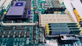
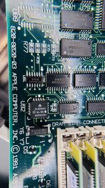
I took the motherboard out, looks pristine, no corrosion at all, no signs of unsoldered pins at U92. Y6 looks fine too. Y7 it's empty.
By no means I'm an electronics expert, so bear whith me, what kind of signal should I get in U92 & Y6 if I connect an osciloscope?
 

Phipli

Well-known member
I'd check to see that there is a 1hz signal at pin 43 on... I think VIA1 (U25)?

That signal triggers an interrupt that advances the system clock in the finder.

I don't have a Q700 schematic so I'm having to pull the pin number from the IIci and the chip details from a Google search of photos, but it should be right.
 

danny.gonzalez.0861@gmai

Well-known member
Thanks guys, so turn out the clock does advance when the system is power down. Only when it's power on the clock doesn't advance.
I took the motherboard out, looks pristine, no corrosion at all, no signs of unsoldered pins at U92. Y6 looks fine too. Y7 it's empty.
By no means I'm an electronics expert, so bear whith me, what kind of signal should I get in U92 & Y6 if I connect an osciloscope?
I have no other advice but I am now interested in the outcome so please keep us posted!!

Good luck!
 

dramirez

Well-known member
<a spam message was originally quoted here>

It does, so the RTC may be working correctly.

I tried Snooper 2.0, and funny thing happens, when the Clock test it's running my clock gains 6 seconds which it's the time the test takes to run, every time I run the test I gain 6 secs...

I opened the case, checked voltages, 12.21 and 5.052 volts. Then connected the oscilloscope and got nothing on pin 1 at the RTC... me heart sunk, checked Y6, nothing at all there too. Then went to Y1 and saw a 22.58 Mhz signal, wen back to Y6, nothing...

And then I remember reading somewhere an oscillator clock not working until heated... nothing to loss here be trying, so I got the hot air station and what do you think... my SuperClock started blinking! At 190F Y6 starts working, me RTC is fine, yay!

Now I'm looking for a part to replace, by my measurements Y6 it's a 3x10mm, at first glance this one should work, right?
 

Attachments

  • Q700mobo.jpg
    Q700mobo.jpg
    760.1 KB · Views: 11
  • RTC.jpg
    RTC.jpg
    654.7 KB · Views: 11
Last edited by a moderator:

Phipli

Well-known member
It does, so the RTC may be working correctly.

I tried Snooper 2.0, and funny thing happens, when the Clock test it's running my clock gains 6 seconds which it's the time the test takes to run, every time I run the test I gain 6 secs...

I opened the case, checked voltages, 12.21 and 5.052 volts. Then connected the oscilloscope and got nothing on pin 1 at the RTC... me heart sunk, checked Y6, nothing at all there too. Then went to Y1 and saw a 22.58 Mhz signal, wen back to Y6, nothing...

And then I remember reading somewhere an oscillator clock not working until heated... nothing to loss here be trying, so I got the hot air station and what do you think... my SuperClock started blinking! At 190F Y6 starts working, me RTC is fine, yay!

Now I'm looking for a part to replace, by my measurements Y6 it's a 3x10mm, at first glance this one should work, right?
If the RTC is working at all, I don't think it is the oscillator, given you say it keeps time in the background (needs the crystal) and it doesn't throw an RTC error in Snooper (so I guess can be talked to, which needs the crystal as well). It's more likely that there is an intermittent connection close by, that the heat helped with. Try using the plastic end of a pen to poke RTC and VIA 1 pins. See if touching any areas cause superclock to start blinking.

My suspicion is that it is to do with the 1hz output, did you measure it? It is slow enough that all you need is a meter, or an LED and resistor with flying leads.
 
Last edited:

cheesestraws

Well-known member
My suspicion is that it is to do with the 1hz output, did you measure it? It is slow enough that all you need is a meter, or an LED and resistor with flying leads.

Agreed. This is pretty diagnostic that either the 1s strobe thingy isn't being generated at all or is disappearing between where it's generated and where it ought to get to.
 

dramirez

Well-known member
No, I didn't check for the 1Hz signal, I will. Then I'll do the plastic tip trick. I guess I could do a little retouch on every pin near the RTC.

Thanks for the tips guys.
 
Top