• Updated 2023-07-12: Hello, Guest! Welcome back, and be sure to check out this follow-up post about our outage a week or so ago.

Classic: Clock won't run

LaPorta

Well-known member
So I just re-caped a Classic that I received from someone. Now, I have no idea if the clock worked before (didn't check), but currently something bizarre I have never seen before is going on: The clock won't advance time. I set the clock to the correct time last night, and it just stays where it is: 9:15:00. The seconds don't run, and time and date do not advance. I have never, ever seen this before. Anyone know what might be going on?


Bolle

Well-known member
Either your RTC chip, the crystal for the RTC or a trace connection between those two is broken.

Could also be a broken trace for the 1Hz clock signal from the RTC to the VIA.


LaPorta

Well-known member
Any of that possibly related to the work I did? I replaced all caps and nothing else.


Bolle

Well-known member
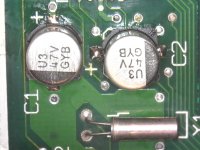
C1 and C2 are really close to the clock crystal and the RTC. It’s possible you damaged a trace but it could also be related to damage from cap goo.

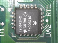
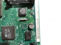
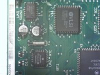
Can you take a high res picture of the area around RTC and VIA?


dochilli

Well-known member
The solder of the crystal does not look very good. I would resolder it.

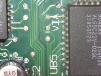
And one connection between UB5 and C2 seems to be corroded.

 
Last edited by a moderator:

Bolle

Well-known member
Traces look fine so far.

Can you remove C2 again? The trace carrying the 1Hz signal from the RTC to the VIA goes right there in the middle of C2's pads.

The soldermask might be damaged right under the cap and you could be shorting that signal to ground. I had this happen before in the audio section of an SE/30... the leg of one of the caps was touching the bare trace shorting it to ground.

Check if all the connections on the RTC are ok and not shorted anywhere:

Bildschirmfoto 2019-10-06 um 11.12.19.png

If they are good I would go on and measure if the crystal is putting out anything. If it does see if the RTC outputs the 1Hz clock signal (pin 2 on the RTC, 43 on the VIA)

The other three signals between VIA and RTC are Data (RTC pin 13), serial clock (RTC pin 19) and chip select (RTC pin 12).

 
Last edited by a moderator:

LaPorta

Well-known member
Bear with me, Bolle, as I have to be at work for 24 hr., so I will not get to this until Monday. How does one go about measuring the crystal? The 1 Hz clock signal I assume will just be a simple wave on the scope. How about the crystal?


Bolle

Well-known member
The 1Hz signal is more like short 5V pulses. One probe on ground, the other one on pin 2 of the RTC.

To probe the crystal just put one probe on each side of it. This should give you a nice 32kHz wave.


LaPorta

Well-known member
Ok, thanks for waiting for a day. The crystal does output 32kHz on one leg according to my scope. On the other, however I get a frequency of 8-13kHz. Is this an issue? Pin 2 of the RTC gives me a constant 60Hz wave with no pulse. This is all with the battery installed only: I can't rig this up in the Classic with power applied.

Take into account also that I am brand new with using a scope, this could be my doing. I can always get photos of what I see.


Bolle

Well-known member
The crystal does output 32kHz on one leg according to my scope. On the other, however I get a frequency of 8-13kHz.
That's ok I guess.

Pin 2 of the RTC gives me a constant 60Hz wave with no pulse.
That's not ok. I think it's doing nothing and the 60Hz you measure might come from the mains? It should really be short 1Hz PWM-like pulses. At least that's what is supposed to do when it's compeltely powered on, not sure if it does the same thing when it's powered by the battery.

Got a way to make an extension wiring harness to power the board while it is sitting next to the chassis, so you can do measurements while the thing is running? A cheap ATX extension with the connector cut down usually works well for that.

Different question: Does it remember the time and other PRAM settings when powered down? (battery in place of course)

 
Last edited by a moderator:

LaPorta

Well-known member
I did make a very nice extension for my SE; of course, I didn’t realize that instead of a female jack like on the SE analog board, the Classic harness is soldered directly to the board. I’d need to make a female-male extension.

Here is where it gets interesting: it does remember the date and time, but, occasionally, the time is a bit more advanced when I turn it on. Not by an appropriate amount, but still some. It does not advance while on and I can see it. So, yes, the memory to store the date and time

is functioning. The other PRAM settings (volume, mouse tracking, brightness, etc) are also preserved.

i will endeavor to either make an extension or just insulate the main board while

having the power on and get back to you if it’s any different.

 
Last edited by a moderator:

LaPorta

Well-known member
Boy, this thing really is baffling. So now depending on whether or not I have the thing hooked up to power, I get different waves and frequencies from the crystal. Having the board plugged into the analog board, not even turned on, changes the wave. Turning it on does that as well. Every time that I turn on the machine, the time has blown ahead by hours sometimes. Something is definitely wrong...could the crystal be bad?

The other possibility is I may not know what in the world I am doing with the scope...

 
Last edited by a moderator:

LaPorta

Well-known member
Ok, so, yes...I reset the scope so it wasn't acting weird. When I hook the probe to the crystal leg when hooked to nothing but the battery, I get the constant 32 kHz wave. The instant I plug the wire harness from the analog board to the main board, I get a huge, fat, constant wave (extremely fast freq). Flipping the machine on drops the amplitude of that wave by a factor of about 4....but still nothing of any value. When I then shut it off and disconnect the cable, the wave dissipates over a few seconds back to 32 kHz. Does this mean that there is some aberrant current making the crystal vibrate tremendously, throwing off the timing circuitry? Just a total hunch since this is not my thing.

So I checked voltages between the legs of the crystal with the voltmeter. With just the battery, I get a fluctuating 0.2-0.6 volts that oscillates up and down (ticking of the clock, no doubt) which is what I would assume would happen. With the machine switched on, I get a steady 1.7 volts, in the opposite direction (negative) with no variation. I assume that should not be, and explains why the clock will not "tick." Having the Classic schematics would help greatly, but I can't find them.

 
Last edited by a moderator:

LaPorta

Well-known member
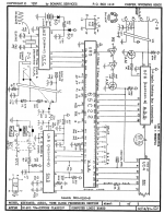
Thank you very much for that, I was unable to locate them online myself (at least in a format I could open).

It would appear on these schematics that the ~32 kHz signal comes from the side that I have been measuring it from (which is good). C69 and C68 run under the board, and I tested them to make sure they test well (they do). I can see where power enters from the battery...I may need to test C67 and D1/D2 to see if there truly is only one-way flow. If one of the diodes is shorted or no longer holding back reverse current, perhaps that could explain some of this. More investigating...

On a side note: is there any resource you could recommend for using the scope? How did you learn to use it as well as you have?


LaPorta

Well-known member
SOLVED!!!!!!

Bolle, I can't thank you enough for the schematics, they made all the world of difference!

So, diode D2, which accepts the incoming power from the main board in lieu of the battery, was shorting out to it's non-conducting terminal (it's one of those three-leg ones where one is cathode, one anode, and one just holds it in place). Somehow, this was causing the signal to get distorted and not be the normal, 32 kHz crystal signal (as I witnessed on the scope when I would connect the analog board). I figured this out because I was getting the same voltage on the anode and the non-used leg, which should not happen at all. I desoldered it, and noticed some cap goo underneath, which I think was causing the short. Cleaned that up, re-soldered, turned her on and bam...clock runs! I would have never been able to hunt this down without the schematics...I appreciate this!

I wonder if anyone else has ever had this crazy issue.

 
Last edited by a moderator:
Top