• Updated 2023-07-12: Hello, Guest! Welcome back, and be sure to check out this follow-up post about our outage a week or so ago.

Classic Analog Board - Thar she blows!

stickyc

Member
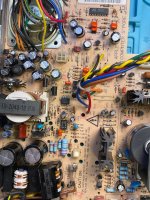
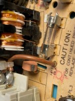
I'm trying to revive a dead Mac Classic - the analog board was in pretty sad shape with the existing capacitors having leaked all over. I scrubbed it clean and recapped it - put it back in, turned it on and nothing happened. I noticed the fuse was blown, so I put in another 3A 250v fuse, flipped the switch and got a beauty of an arc near the fuse and RP2.

There's now a lovely scorch mark on RP2 (what is that anyway??) and another blown fuse.

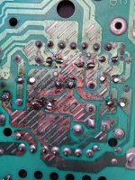
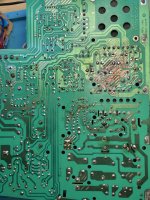
Even though the back of the board looks bad, I checked continuity and it doesnt seem like there's any open solder joints or shorts between major circuit runs. Any ideas what else to look at?

Is it 'safe' to energize the analog board without it being connected to the monitor and motherboard (assuming I've got the flyback lead taped down and far away from anything conductive)? I'd love to be able to test the thing without actually connecting it up and frying more parts.
IMG_0027.jpeg

IMG_0026.jpeg

IMG_0025.jpeg

IMG_0024.jpeg


bibilit

Well-known member
have a look at the Mosfet (IRFBC40... IIRC) known for having this kind of behavior on the fuse, most of the times shorted.

The other issue is having a shorted bridge rectifier, happened to me once, pretty rare issue.


mogs

Active member
This looks pretty similar to what happened to my Classic II AB. Certainly the big MOSFET shorting is the most likely culprit. Although, in my case at least, it seems that the circuit can end up with such low impedance that a replacement fuse will draw very large currents before blowing taking out RP2 and who know what else in the process (I was lucky to be working from a sub-main at the time so I didn't take out the whole house, just the shed  8-o  ).

By this time I had already successfully worked out a proof of concept for running it from ATX power, so I decided to remove all of the AC circuitry and do that instead. Pretty happy with the results.

I'm currently waiting on parts to assemble a non-destructive ATX power injector, I'll update my thread if I get that working. Should be a nice tool for quickly testing logic boards if nothing else.


mogs

Active member
In answer to your question: RP2 is a NTC (negative temperature coefficient) resistor. This limits inrush current (due to relatively large values of capacitance CP1, CP13) when power is applied to the circuit. The cold resistance slows down the charging of those capacitors, when normal operating current flow is established the NTC self heats and the resistance reduces accordingly.

When cold RP2 should be 12 or 20ohms depending on AB version (12 for yours I think), you should be able to test this in circuit with a multimeter (with power removed obvs). I suspect you will find it has gone open circuit or high resistance as a result of the fault current. It might also be short circuit which would also be bad.

Try removing the MOSFET QP2 IRFBC40 and test it, I would anticipate there to be short circuit from drain to source (pin 2,3). A good MOSFET of this type should conduct S->D but not D->S using diode test mode.

That area you took the closeup of the back of board (top photo) is the DC outputs which shouldn't see high voltages (-12, 5, 12 and ~36V on the highest tap) looks more like capacitor vomit to me? Perhaps just give it a good clean.

The next photo you can see some discolouration under CP13 and CP1 (the big capacitors) and RP1 (another NTC in early ABs?). If you've replaced those caps it's probably just residue, if you haven't replaced them you might want to pull them and test them (careful, they might be charged to high voltage). I guess another possibility is that without functioning inrush protection these got hot when power was applied and caused the discolouration.

Good luck.


stickyc

Member
I measured about 2ohm across RP2, so it's for sure toast. I'll see if I can test the MOSFET.

Yes, there was a lot of capacitor vomit. That's actually after spending time with a toothbrush and 99% rubbing alcohol (hence the removal of a lot of the green coating). I've replaced all of them as part of this refurb.

Thanks for the pointer! Hopefully that'll work.


cheesestraws

Well-known member
Do test the bridge rectifier as well.  It's not a common failure, but it does happen, and while you're poking things with the multimeter you might as well do so :) .  For me, with vaguely similar symptoms, two diodes in the bridge rectifier had stopped being diodes and started conducting in both directions.

 
Top