• Updated 2023-07-12: Hello, Guest! Welcome back, and be sure to check out this follow-up post about our outage a week or so ago.

Checker-board screen with 68030 Performer Accel in Mac SE

DrGonzo

Active member
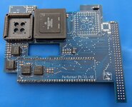
So to anyone wanting to build up a Performer and planning to buy the 96 pin EuroDIN connector... probably hold off. My 68030s came in unexpectedly today so I went to install the finished product in my primary SE and it DIDN'T FIT. :(

The EuroDIN increases the height by only a millimeter or so, but it's enough where the CPU no longer has enough clearance from the bottom of the case. It pushes it down a bit so technically it did go in, but not before I had to pull the crystal for the 68882 off as it was the highest part. Worse yet, it caused a big scratch on the top of the 68030 from the case.

68030.jpg

I'm likely going to have to hard solder the crystal after removing the socket, and then possibly remove the EuroDIN and just put pin headers on like my original prototype from above.

FWIW,
~Dr. G
 

Bolle

Well-known member
The original has the CPU soldered down.
So it’s not the DIN connector that’s at fault but the extra height that’s added by the CPU socket.

Also there’s two different chassis types and one of them has less clearance in that area if I remember right.
 

DrGonzo

Active member
Ah, that makes sense. I'll have to pop the top open on another SE and see if I might have a different chassis that's more forgiving. I do see now that your build has a much recessed CPU with being soldered in, so that makes sense as well. I will say that my EuroDIN is likely making things even worse as it does raise the card up a bit:

Headers.jpg

I'd noticed the OG from MicroMac Tech was socketed, but also didn't have the EuroDIN but the killy clip so seemingly wasn't meant for the SE either. Ah well, live and learn. Thanks for the clarification and for taking the time to reverse engineering the Performer and Tokamac for the community!

Hopefully this didn't come off as critical of the project. Just sharing my experience with the build to help others. ;)

Regards,
~Dr. G
 

Phipli

Well-known member
Ah, that makes sense. I'll have to pop the top open on another SE and see if I might have a different chassis that's more forgiving. I do see now that your build has a much recessed CPU with being soldered in, so that makes sense as well. I will say that my EuroDIN is likely making things even worse as it does raise the card up a bit:

View attachment 57827

I'd noticed the OG from MicroMac Tech was socketed, but also didn't have the EuroDIN but the killy clip so seemingly wasn't meant for the SE either. Ah well, live and learn. Thanks for the clarification and for taking the time to reverse engineering the Performer and Tokamac for the community!

Hopefully this didn't come off as critical of the project. Just sharing my experience with the build to help others. ;)

Regards,
~Dr. G
For one of my accelerators I have to leave one screw out of the hard disk bracket or it catches badly on the RAM on the accelerator. Bit of a pain. I might try finding a countersunk screw for it instead of the cheese head that was stock to see if it improves clearance. Wish I had the original manual to see what it said about it.

Perhaps I should make some custom RAM with a notch in the right place for the screw :ROFLMAO:
 

DrGonzo

Active member
Heheh, funny you mention that as I'd pulled that same screw out this weekend to see if it would make a difference in the clearance on my Performer. It still pushed down at an angle due to the height of the EuroDIN and sockets, but I think it's not gouging the CPU anymore. Some progress I guess until I figure out how I want to switch over to pin header for the connector. I really don't want to pull the CPU socket and solder in the proc if I can avoid it.

Later,
~Dr. G
 

JC8080

Well-known member
I just finished my build (photo attached), and I am having the same issue, I get a checker-board screen on boot. I made sure to use the rev D GALs. Here are some notes on my build:
- 16V8D GALs programmed with T48 programmer and Xgpro software. I used the "GAL16V8D" IC setting, there was also "GAL16V8D @SOIC20" that I did not use.
- I was very careful to make sure each GAL has the correct image, I marked each one with tape immediately after burning, and confirmed each GAL is oriented correctly on the board (by the silk screen on the board, and reference photos of Bolle's completed board)
- I had a lot of trouble soldering the GALs to the board so I ended up using solder paste, and then using my iron on each leg to make sure the paste was fully melted. I inspected the joints with a microscope and then checked continuity on every leg of each GAL.
- I ordered two '030 CPUs from eBay, they were supposed to be new, but the dinged-up housings suggest otherwise. I tried both CPUs, no change in behavior. It is possible both are bad, but not too likely.
- Since I am going to use this in my SE first, I did not install GAL U7, and I bridged the pads at SJ2 (not shown in photo)
- For the CPU socket and PDS pin header I was very careful with my soldering, and inspected the joints with a microscope. I think it is unlikely there is a solder joint that did not take properly.
- I did not install the FPU or FPU crystal for testing.

I want to see if anyone has troubleshooting suggestions before I start checking continuity on everything, since that will be quite time consuming. The test machine is a known-good SE with a known-good PDS slot (used with other accelerators). I am hoping I am just overlooking something simple.
 

Attachments

  • PXL_20230704_163205691~2.jpg
    PXL_20230704_163205691~2.jpg
    1.4 MB · Views: 22

DrGonzo

Active member
I just finished my build (photo attached), and I am having the same issue, I get a checker-board screen on boot. I made sure to use the rev D GALs. Here are some notes on my build:
- 16V8D GALs programmed with T48 programmer and Xgpro software. I used the "GAL16V8D" IC setting, there was also "GAL16V8D @SOIC20" that I did not use.
- I was very careful to make sure each GAL has the correct image, I marked each one with tape immediately after burning, and confirmed each GAL is oriented correctly on the board (by the silk screen on the board, and reference photos of Bolle's completed board)
- I had a lot of trouble soldering the GALs to the board so I ended up using solder paste, and then using my iron on each leg to make sure the paste was fully melted. I inspected the joints with a microscope and then checked continuity on every leg of each GAL.
- I ordered two '030 CPUs from eBay, they were supposed to be new, but the dinged-up housings suggest otherwise. I tried both CPUs, no change in behavior. It is possible both are bad, but not too likely.
- Since I am going to use this in my SE first, I did not install GAL U7, and I bridged the pads at SJ2 (not shown in photo)
- For the CPU socket and PDS pin header I was very careful with my soldering, and inspected the joints with a microscope. I think it is unlikely there is a solder joint that did not take properly.
- I did not install the FPU or FPU crystal for testing.

I want to see if anyone has troubleshooting suggestions before I start checking continuity on everything, since that will be quite time consuming. The test machine is a known-good SE with a known-good PDS slot (used with other accelerators). I am hoping I am just overlooking something simple.
Couple thoughts...

- it might be just the angle of the pic, but U6 looks off center on the pads. I'd go around each GAL with a meter to make sure no shorts with the next pin over. I think there is one set that is supposed to be connected to the next one, but that should be the same across all of them so should be consistent. I can try to confirm later when I'm in front of one again.

- Did you verify each GAL in XGPro after programming to make sure they took?

- Any chance the pin header for the 68k socket is making contact with the SE board when seated in the PDS slot and shorting out?

Otherwise looks very clean. Hope it turns out to be a quick fix. Good luck!

~Dr. G
 

JC8080

Well-known member
Couple thoughts...

- it might be just the angle of the pic, but U6 looks off center on the pads. I'd go around each GAL with a meter to make sure no shorts with the next pin over. I think there is one set that is supposed to be connected to the next one, but that should be the same across all of them so should be consistent. I can try to confirm later when I'm in front of one again.

- Did you verify each GAL in XGPro after programming to make sure they took?

- Any chance the pin header for the 68k socket is making contact with the SE board when seated in the PDS slot and shorting out?

Otherwise looks very clean. Hope it turns out to be a quick fix. Good luck!

~Dr. G

U6 is a bit rotated, I didn't notice until after it was fully soldered down. :rolleyes: It drives me up the wall. Once I get the board working I'll straighten it out, I decided I'd leave as-is while I troubleshoot since the continuity seems fine.

I checked continuity with the adjacent pins for all the GALs, two of the pins on U6 are connected, circled in the diagram below. Based on the gerber file it looks like both those pins go to the same middle layer (ground? 5v?), but I'm not certain. I did carefully inspect those two pins with a microscope and used a pick between them to check for a bridge, everything seems fine. If you could confirm on your board that would be helpful.

Yes, the GALs were all verified when I first programmed them last week. Then when I went to install them yesterday, I put them into the programmer and ensured they can be read.

The 68k header is ok, that's a socket soldered to the bottom of the board, so there aren't any pins hanging down. It will slip over the pins soldered to the 68k on my Plus. I also test-fit the card to my SE board and checked to make sure nothing could touch or short.

Thanks for the compliment, I spent quite a bit of time lining up those resistors.

1688522335996.png
 

DrGonzo

Active member
So just checked mine and pins 10 and 11 show continuity on both U5 and U6. Not on the other two though interestingly enough. The other thing I notice (but not sure it would keep it from coming up) is do you have the solder blob across SJ1? It may be looking for the crystal even though you don't have the math chip in and getting confused? Total shot in the dark, but any easy test I guess. Frustrating though for sure!

Keep us posted,
~Dr. G

GAL16V8D.JPG
 

JC8080

Well-known member
So just checked mine and pins 10 and 11 show continuity on both U5 and U6. Not on the other two though interestingly enough. The other thing I notice (but not sure it would keep it from coming up) is do you have the solder blob across SJ1? It may be looking for the crystal even though you don't have the math chip in and getting confused? Total shot in the dark, but any easy test I guess. Frustrating though for sure!

Keep us posted,
~Dr. G
Thanks for confirming the continuity on those pins. No, I did not bridge SJ1, definitely worth a shot. I've started checking continuity on all traces, it's tedious but not terrible since I have the gerber file to follow. This will at least eliminate one source of potential issues.

When I programmed the GALs in Xgpro I unchecked encryption, unchecked LOCK Bit, and left FLASH checked. I looked through the manual and did some online searches and wasn't able to figure out exactly what LOCK Bit and FLASH do, so I gave it my best guess. Do you recall which settings you used when you programmed your GALs?
 

DrGonzo

Active member
Thanks for confirming the continuity on those pins. No, I did not bridge SJ1, definitely worth a shot. I've started checking continuity on all traces, it's tedious but not terrible since I have the gerber file to follow. This will at least eliminate one source of potential issues.

When I programmed the GALs in Xgpro I unchecked encryption, unchecked LOCK Bit, and left FLASH checked. I looked through the manual and did some online searches and wasn't able to figure out exactly what LOCK Bit and FLASH do, so I gave it my best guess. Do you recall which settings you used when you programmed your GALs?
As I recall, the only setting I changed was turning off encryption. Otherwise left it default.

~Dr. G
 

JC8080

Well-known member
I spent more time today than I will admit checking continuity of every trace on the board, everything checks out fine. I looked at SJ1, one side goes directly to a pin on the FPU. Since I don't have an FPU installed, I don't believe bridging will have any effect, since it will still be an open circuit.

I am going to try programming a new set of GALs and see how that goes. It seems that I have narrowed it down to either the GALs or the passive components - I think it is much more likely it is the GALs than the caps or resistors.
 

JC8080

Well-known member
I programmed new GALs, and it now works. I am not sure if the problem was the actual GALs, or how i programmed them the first time. For anyone looking to do this in the future, the settings that worked for me with Xgpro are as follows:
IC: GAL16V8D @SOIC20 (the first time I used the non-@SOIC20 setting, I don't know if this caused the problem, but @SOIC20 did work for me)
Encryption: off
LOCK bit: on (default)
FLASH: on (default)

I just did a quick check with Speedometer 3.06, I get the same 3.3x faster that @DrGonzo did. Once I install the FPU and crystal I will take some photos of the board and do another benchmark to see the impact of the FPU.
 

DrGonzo

Active member
Glad to hear you got it going! Sounds like similar issue I'd had but, due in my case, to having the wrong GAL revs. 😋

I still haven't had the chance to remove the EuroDIN and/or the 030 socket to fix my clearance issues. So many projects, so little time...

~Dr. G
 

zigzagjoe

Well-known member
FWIW, I am using some NOS GAL16V8D in another project and have had a strange issue with them. My programmer (T48) selects 16v VPP by default, and the GALs program and verify fine at this voltage. However, they don't act correctly and logic tests fail. Upping the programming voltage to 17v addresses the issue (and they program fine at 16v afterwards, which is the weirdest part).
 

Phipli

Well-known member
FWIW, I am using some NOS GAL16V8D in another project and have had a strange issue with them. My programmer (T48) selects 16v VPP by default, and the GALs program and verify fine at this voltage. However, they don't act correctly and logic tests fail. Upping the programming voltage to 17v addresses the issue (and they program fine at 16v afterwards, which is the weirdest part).
How confident are you that they are NOS, and not relabelled ones? Do you have a photo of the pins on one?
 

zigzagjoe

Well-known member
How confident are you that they are NOS, and not relabelled ones? Do you have a photo of the pins on one?
They're from a reputable US vendor. Supposedly were originally ordered programmed (and are engraved), leads are clean and supplied in a strip. I believe them to be legit, and propagation delay appears accurate.

Couldn't tell you if it's a quirk of the D variants or what, the lack of specific detail from lattice is pretty annoying.
 

zigzagjoe

Well-known member
Oh, sorr
That sounds reasonable :)

Lots of resurfaced chips are laser engraved though, just so you realise.
Oh, sorry, I meant engraved with details of programming. Along with the original markings. They're legit, just wanted to mention the possible need to increase programming voltage with these chips as to all appearances they were OK except for, you know, not working.

Incidentally, the supplier was https://specialtypartsinc.com. They also were able to get me some TAG SRAMS which are very hard to come by.
 
Top