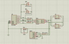
Just to get the diagrams in question into one place, here's the diagram from A-4

... and here's the diagram from A-6 and A-7

It looks like the 'computer' side of the transformer is center-tapped, but the A-4 diagram is slightly contradictory as to how it is wired up - if you believe the turn count on the A-4 diagram, then only one half of the computer-side winding (35 turns) is being used, effectively giving a 1:2 ratio. But if you believe the pin numbers, then the whole winding is used with the center tap left disconnected.
Regardless, the transformer in the adapter that I cracked open is definitely not center-tapped on either side, and since the inductances on both sides of it are roughly the same, then I'm pretty sure that the turn counts are probably the same.
... and here's the diagram from A-6 and A-7
It looks like the 'computer' side of the transformer is center-tapped, but the A-4 diagram is slightly contradictory as to how it is wired up - if you believe the turn count on the A-4 diagram, then only one half of the computer-side winding (35 turns) is being used, effectively giving a 1:2 ratio. But if you believe the pin numbers, then the whole winding is used with the center tap left disconnected.
Regardless, the transformer in the adapter that I cracked open is definitely not center-tapped on either side, and since the inductances on both sides of it are roughly the same, then I'm pretty sure that the turn counts are probably the same.
")