• Updated 2023-07-12: Hello, Guest! Welcome back, and be sure to check out this follow-up post about our outage a week or so ago.

Backwards progress with SE/30

ironhalo

Active member
Hello all. Longtime lurker, first time poster. It has been while since I owned a compact Mac, but recently came across an SE/30 for sale that was in surprisingly good shape. The seller insisted on booting it several times to show me it worked, and it seemed to boot fine to the internal SCSI, but had no audio. The external floppy connector also did not work.

I decided to have some fun with it so I ordered recap kits from Console5 for the logic board, analog board and Sony power supply. Before those arrived however I got my hands on a new 1/2AA battery, a Mac ROM-inator II, some new RAM from OWC, and a SCSI2SD unit. I installed the new ROM, RAM and SCSI2SD, and everything was still working quite well (minus audio). I was able to make fresh installs of system 6 and system 7 on the SCSI2SD with no problems (using my BMOW Floppy Emu that I'd acquired a while back for my Apple IIe projects).

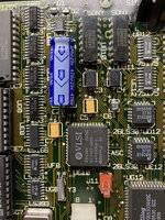
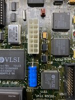
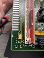
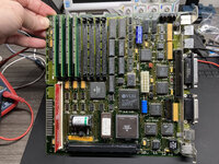
So then the recap kits came in and I got to work on the logic board (have not touched the analog board or power supply yet). I removed the 13 caps, then cleaned the board several times with 99% isopropyl and a tooth brush. While it was obvious many of the caps had leaked, the corrosion could have been much worse. I saw no darkened traces, but I did see a few traces that looked partially exposed, so I covered those up with some UV resin before soldering anything. I replaced the caps with the ones from my Console5 tantalum kit, with the exception of C3, C4, C9 & C10, which I replaced with uprated 25V 47uF tantalum caps I got from Mouser. In the process I noticed that transistor Q3 had gone missing from corrosion, so I replaced that with a 2N3904 (did not have a surface mount MMBT3904 available). I then buzzed out all the traces to/from each capacitor to make sure my soldering was good, and I checked for accidental bridging with adjacent traces. All looked good.

I put the new ROM, new RAM, and battery back in it and fired it back up. Sadly, it now seems to be in a much worse state than before. You can see from the video that it displays typical simasimac video artifacts, and now has a fast ringing audio pattern which changes pitch after several seconds. I am a couple of days into troubleshooting, but have not made any progress at all. Below is what I have done so far, to no avail:

- Cleaned and re-seated ROM and RAM
- Swapped back to original ROM and original RAM, and also tried mixing old and new
- Double checked continuity on all capacitor traces, and double checked for bridging to nearby traces
- Downloaded all the schematics and successfully buzzed out traces between ROM, RAM, CPU and GLUE
- Tried pulling up UB11 audio chip with a 1K resistor across pins 7 and 15 (this turned the audio ringing into audio clicks, but did nothing else)
- On a whim, removed the 2N3904 at Q3 (simply to test, since the board had been working fine without it before)

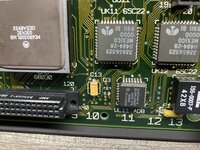
TL;DR... None joy with any of the above. So in summary, the board was working well before my clean and recap, and now it's simasimac. I cannot see any darkened traces, and have successfully buzzed out most of the traces that people typically suggest would be related to these issues. I have found no discontinuity or bridging. The most corroded component seems to be UE8, but its traces seem fine.

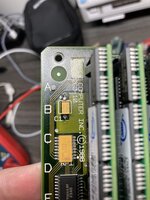
I seem to be running out of common trouble shooting steps, with the exception of replacing the RP2 network filter. Is there any way to test it to see if it's bad? Though I don't know how likely it is that it spontaneously went bad as a result of my recapping...?

Any suggestions on where to go next with this board? Many thanks in advance. Video link below and hi-res photos attached.


VIDEO LINK:
 

Attachments

  • IMG_4698.jpg
    IMG_4698.jpg
    4.2 MB · Views: 28
  • IMG_4699.jpg
    IMG_4699.jpg
    2.5 MB · Views: 28
  • IMG_4700.jpg
    IMG_4700.jpg
    2.9 MB · Views: 25
  • IMG_4701.jpg
    IMG_4701.jpg
    1.4 MB · Views: 26
  • IMG_4702.jpg
    IMG_4702.jpg
    2.1 MB · Views: 27
  • IMG_4703.jpg
    IMG_4703.jpg
    3.9 MB · Views: 30
Last edited:

Nixontheknight

Well-known member
that's your problem. Measure how much voltage is coming out of the power supply, you should have easy access to the 5V and 12V rails on the Molex connector. If they are under 5V, then the 68000 will not get sufficient power
 

Nixontheknight

Well-known member
Thanks for the reply but sorry, what's my problem?

I'm getting 5.33V and 12.6V at the molex connector without the logic board connected, and 5.09V and 12.05V with the board connected
your problem is that you haven't recapped the power supply yet. Maybe the capacitors inside the power supply are marginal and not providing enough current to the logic board for it to power on.
 

ironhalo

Active member
Ah, got it. So even though it's testing above 5V, and even though it was providing enough power in prior testing, that could have changed now that I've recapped the board? The new caps are drawing more current than the old ones were, and that perhaps is pushing the PSU over the edge?
 

Nixontheknight

Well-known member
Ah, got it. So even though it's testing above 5V, and even though it was providing enough power in prior testing, that could have changed now that I've recapped the board? The new caps are drawing more current than the old ones were, and that perhaps is pushing the PSU over the edge?
potentially, I'm not sure, but you're always supposed to recap the analog board, power supply, and logic board all at once for optimal performance. If recapping the board doesn't work, then I don't know what to tell you.
 

ironhalo

Active member
Makes sense that you'd do them all at once, but since it's my first Mac recap I thought I'd test in between doing each board. Wanted to limit the number of variables in case I ended up in this scenario and had to start troubleshooting. I guess I'll move forward with the PSU and keep my fingers crossed that does the trick. Thanks for the replies.
 

Johnnya101

Well-known member
I'm seeing a lot of corrosion still present on that board. I'm not sure if it is your problem, but you should really try and remove it all and see if anything improves.

The power supply probably isn't at fault here, although it is a good idea to redo it since you've got everything kind of apart anyways. If it worked before, it should work now.

UE8 is for video, so I don't think it could cause an audio issue like this?

Also, for Q3, you sure that was missing when the computer was on and working? Could it have fallen off during replacing caps? The traces for it look a little iffy, might want to check those pads/traces and replace Q3 again.
 

craig1410

Well-known member
Hi - a few thoughts:

I see signs of solder balls or other debris in the close-ups. Is it possible that you dislodged a piece of solder when cleaning and it has now shorted something unrelated to the recapping? Maybe try a thorough cleaning of the whole board, maybe even with water/windex etc as well as a thorough scrub with a tooth brush again? Compressed air can be handy for blasting debris out as well as cleaning water/IPA from under the ICs. Always ensure it's fully dry before powering up again.

Maybe it's just the photos so please forgive me if I'm speaking out of turn but the soldering on the new caps looks like maybe it needs some flux to get a better flow as it looks a little bit uneven. This can also happen if you are soldering in very low ambient temps. Note that it's generally not a great idea to apply any more heat than necessary to tantalum caps so feel free to ignore me if you feel the solder joints are all good. It's impossible for me to judge from a single angle photo.

Using the schematics, check what voltage you should be seeing at each cap and check them with a meter to see that they are correct. Bear in mind that some are negative voltages in which case the +ve of the cap will be attached to ground and you need to read the voltage from the negative end of the cap instead. Also, try to check voltage to the caps themselves not just the PCB pads so that you are checking the solder joint at the same time.

If the caps all read the correct voltages then I'd guess you've either created a solder bridge by dislodging some solder or you've got a dry joint due to generally handling/flexing of the PCB, especially around some of the corroded chips. Ideally you've want to remove the corroded chips completely along with all the old solder and reattach them with fresh solder after cleaning the pads carefully, but reflowing the pins in the presence of some flux might be good enough to see if you're on the right track.

I'm not familiar with what you were hoping to achieve by putting a 1k resistor for UB11 pins 7 to 15? Pin 6 on UB10 and UB11 is the voltage sense for the reset circuitry if that's what you were trying to pull up? It should already be getting pulled up by the 27 ohm R11.

Stick at it - I'm sure the solution will present itself.
 

ironhalo

Active member
Also, for Q3, you sure that was missing when the computer was on and working? Could it have fallen off during replacing caps? The traces for it look a little iffy, might want to check those pads/traces and replace Q3 again.
Pretty sure it was already gone, I noticed it missing before I did any major cleaning or removing.
 

ironhalo

Active member
Hi - a few thoughts:

I see signs of solder balls or other debris in the close-ups. Is it possible that you dislodged a piece of solder when cleaning and it has now shorted something unrelated to the recapping? Maybe try a thorough cleaning of the whole board, maybe even with water/windex etc as well as a thorough scrub with a tooth brush again? Compressed air can be handy for blasting debris out as well as cleaning water/IPA from under the ICs. Always ensure it's fully dry before powering up again.

Maybe it's just the photos so please forgive me if I'm speaking out of turn but the soldering on the new caps looks like maybe it needs some flux to get a better flow as it looks a little bit uneven. This can also happen if you are soldering in very low ambient temps. Note that it's generally not a great idea to apply any more heat than necessary to tantalum caps so feel free to ignore me if you feel the solder joints are all good. It's impossible for me to judge from a single angle photo.
Always possible some solder debris has lodged itself somewhere. That would make more sense to me than some unrelated component(s) spontaneously going bad when everything was working fairly well before the recap. I'll give cleaning another go.

Yeah, the solder job could certainly be cleaner, but I was afraid of heating up the new caps too much and damaging them. I've double checked continuity through every cap from vias or traces on either side of the cap, so I'm pretty confident the connections are good. I may try adding some flux and reflowing some of them for good measure before I do another round of cleaning. Thanks.
 

ironhalo

Active member
I'm seeing a lot of corrosion still present on that board. I'm not sure if it is your problem, but you should really try and remove it all and see if anything improves.

The power supply probably isn't at fault here, although it is a good idea to redo it since you've got everything kind of apart anyways. If it worked before, it should work now.

UE8 is for video, so I don't think it could cause an audio issue like this?

Thanks for the feedback, makes sense.
 

ironhalo

Active member
I'm not familiar with what you were hoping to achieve by putting a 1k resistor for UB11 pins 7 to 15? Pin 6 on UB10 and UB11 is the voltage sense for the reset circuitry if that's what you were trying to pull up? It should already be getting pulled up by the 27 ohm R11.
To be honest I was grasping at straws there and blindly following something I'd read in multiple places. On this page, Section II (Troubleshooting), Item 1 (Simasima), solution (5)...

https://bylenga.ddns.net/SE30 repair.html
 

craig1410

Well-known member
To be honest I was grasping at straws there and blindly following something I'd read in multiple places. On this page, Section II (Troubleshooting), Item 1 (Simasima), solution (5)...

https://bylenga.ddns.net/SE30 repair.html
Thanks for the background on this. I read that article and I still find it a bit baffling why this might help fix simasimac but I understand why you gave it a try. I'm not aware of any data sheets for those sound chips so hard to be sure what those pins actually do beyond basic assumptions.

I think if you focus on cleaning the board using whatever method is appropriate (windex, white vinegar, bicarb, soap, water, gentle agitation, compressed air) and generally have a good look around for solder balls or fine wire strands, that'll be your best bet. If you have access to an ultrasonic cleaner then even better.

Looking forward to hearing how you get on.

And Happy New Year by the way. :)
 

cheesestraws

Well-known member
Sorry for double post, hit reply too early.

That would make more sense to me than some unrelated component(s) spontaneously going bad when everything was working fairly well before the recap.

This'd be my bet too: concentrate on a good deep clean to start with. Examine the solder joints *around* the caps you worked on with especial care.
 

CircuitBored

Well-known member
you're always supposed to recap the analog board, power supply, and logic board all at once

I don't think this is very good advice. Recapping the AB, PSU and LB all at once is a good way to potentially introduce lots of new trouble which you will have a very hard time tracing to its source. Even if you are working on a machine that works perfectly pre-recap you are making things far more difficult than they have to be when it comes to troubleshooting.

My advice would be to recap as little as you can stomach at once. I.E. fewer caps in more batches, testing the board after each batch. I've recapped some devices two caps at a time. By replacing fewer caps at once you are making things a lot easier for yourself if any trouble arises. There's nothing "wrong" with recapping a whole board at once but it is objectively harder to find faults on a board that has had ten or twenty components switched out in one go.
 

ironhalo

Active member
There's nothing "wrong" with recapping a whole board at once but it is objectively harder to find faults on a board that has had ten or twenty components switched out in one go.
This makes a lots of sense to me. If I do another one of these I will likely do it in smaller batches with testing in between.
 
Last edited:

ironhalo

Active member
Looking forward to hearing how you get on.

And Happy New Year by the way. :)

Thanks Craig (and others) for the advice. I have reflowed all my new cap joints with lots of flux and they are looking much smoother. I’ve also tried reflowing some of the chips with the most corrosion evident. I’ll give the board a really good cleaning next and see what happens after a long dry.

Thinking ahead, if that doesn’t fix my issues and I endeavor to completely remove and resolder some of those nasty looking chips (UD8, UE8…), shouldn't i just go ahead and replace them with new chips if I’m going to the trouble anyway? Also considering buying a PLCC socket for the ASC chip in case I end up needing to remove it too. (Placing a Digikey order anyway, so might as well spend a couple more dollars preemptively is my thought.) Any other “usual suspect” components come to kind that I might consider tossing on this order in an effort to avoid placing another order a week from now? RP1 looks a little suspect. I may end up doing more SE/30 work in the future so I'm not opposed to having a few spare components on-hand.

Thanks and Happy New Year to you all!
 
Last edited:

CircuitBored

Well-known member
I’ve also tried reflowing some of the chips with the most corrosion evident.

From my personal experience: if a chip is visibly corroded, it is probably faulty at best.

It's worth thinking about the science of what has happened here. When a capacitor leaks it releases an electrolytic fluid onto the logic board. Once this leakage has a current running through it, it immediately starts doing what electrolytes do: electrolysing. The resistance of the fluid is normally high enough that the machine will keep on truckin' without any issues being initially apparent. All the while, the electrolysis of the fluid keeps eating away at anything metallic that it's in contact with until the damage is significant enough to stop the machine working. If a component was in contact with electrolytic fluid while it was powered, it is going to be damaged to some extent. The fluid has intense penetrating power and will wick up inside anything in the vicinity, causing damage you can't even see.

Replacing UE8 on an SE/30 is pretty much par for the course. I replaced all the chips in that row just to give me peace of mind. These chips are not expensive or hard to find so, in my opinion, it's worth replacing them just to be on the safe side. As mentioned: you really can't see the extent of the damage caused by the old caps.

I strongly recommend that, once you have a bootable machine, you check whether or not your serial ports work. Both the serial transceivers in my machine looked completely fine but had in fact been tanked by capacitor juice. Again, replacements are cheap and readily available.

Best of luck with your repairs and nice job so far!
 
Top