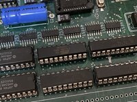
So, build update. Here's the current state of the board:

Pretty close to done. Things left on the to-do list:
I also bought the video ROM socket, CPU socket, PLCC sockets, SCSI, floppy, system ROM, and RAM sockets from Phoenix and they are all fine. The PGA CPU socket had a few pins that were mildly oxidized and took a little extra flux and heat to wet, but that's understandable since these are NOS parts. But the HWS2078 20-pin DIP sockets I would recommend staying far away from.
Speaking of sockets, this was my first time installing PLCC sockets. Based on what I'd seen people on YouTube do, either cutting out the bottom of the socket or using solder paste, I was a little worried about installing these, but it didn't end up being bad at all. A fine tipped iron, flux, and patience, and I found it pretty easy to get into a groove of soldering the pins by hand. I'm happy with how they came out.

Pretty close to done. Things left on the to-do list:
- Waiting for the PLCC to QFP carrier boards from OSH Park for the ADB PIC16
- Solder pins on the Bourns Again filters and install those
- Populate the RTC and surrounding components
- Install the PDS slot
- Oh yeah, NMI and reset switches, need those too; going to try 3D printing the little supports for them
- Waiting for Digi-Key to deliver 20-pin DIP sockets for the PALs
I also bought the video ROM socket, CPU socket, PLCC sockets, SCSI, floppy, system ROM, and RAM sockets from Phoenix and they are all fine. The PGA CPU socket had a few pins that were mildly oxidized and took a little extra flux and heat to wet, but that's understandable since these are NOS parts. But the HWS2078 20-pin DIP sockets I would recommend staying far away from.
Speaking of sockets, this was my first time installing PLCC sockets. Based on what I'd seen people on YouTube do, either cutting out the bottom of the socket or using solder paste, I was a little worried about installing these, but it didn't end up being bad at all. A fine tipped iron, flux, and patience, and I found it pretty easy to get into a groove of soldering the pins by hand. I'm happy with how they came out.
") . I dab a little solder on the iron so that there's a small bead of molten solder sitting on the tip, then touch it where the socket leg and the PCB pad meet. Thanks to the liquid flux, the solder will flow and wet the whole pad and the socket leg and form a smooth, shiny joint. After tacking two corners, I just worked my way around the perimeter, dab, dab, dab, dab. I did all the ones that I could approach from one side first; because of the plastic supports, some legs can only be approached from the left or the right, and I got tired of having to switch positions back and forth, so once I had the socket tacked, I would do all the lefts, then all the rights, and I was able to get into a nice groove and make smooth, consistent joints pretty quickly this way.
. I dab a little solder on the iron so that there's a small bead of molten solder sitting on the tip, then touch it where the socket leg and the PCB pad meet. Thanks to the liquid flux, the solder will flow and wet the whole pad and the socket leg and form a smooth, shiny joint. After tacking two corners, I just worked my way around the perimeter, dab, dab, dab, dab. I did all the ones that I could approach from one side first; because of the plastic supports, some legs can only be approached from the left or the right, and I got tired of having to switch positions back and forth, so once I had the socket tacked, I would do all the lefts, then all the rights, and I was able to get into a nice groove and make smooth, consistent joints pretty quickly this way.