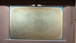
Hi, this is my first post so I apologize if I'm breaking any rules, please let me know. My friend bought a non-functional PowerBook 100; after fully cleaning and recapping, it turns on the backlight, chimes, and makes Mac OS sounds when pressing keys. However, the screen is completely blank:

Obviously, the polarizer needs to be replaced, but we would still expect some discernible image -- particularly because lines show up briefly when pressing the reset button?
Following some other posts and the schematic here, they checked LCD_VEE at TP055 and found 4.7 V rather than the expected -22 V. The inductors L2, L3 and L4 all have continuity, none of the capacitors in the circuit are shorted (and all but the small ceramic SMD ones were just replaced), and they checked continuity on all these traces as well (page 11) by measuring between components at either side:

At one point, the left side of L4 in this schematic read ~0 V while BATT_VOLTAGE (at TP052 and C17) was 7.7 V, so we suspected a broken trace, and my friend added a wire from TP052 to L4. Then they briefly detected -19 V at the top of C22, but the display still didn't work, and LCD_VEE remained at 4 V. We checked DISP_BLANK and ALWAYS ON; both were around 5 V. Confusingly, the -19 V hasn't shown up since, and even after removing the wire, the left side of L4 still reads as 7 V, so we aren't sure if the wire ever did anything at all.
Needless to say, we're extremely confused now. Any ideas what to check at this point? Is it possible for the inductors to be damaged but still show continuity? Is it abnormal for BATT_VOLTAGE to be 7 V rather than 5 V? Are there other points in the LCD_VEE circuit we can check? We only have basic electrical knowledge, enough to read the schematic but not understand how this actually makes -22 V
Thank you in advance and thank you for reading such a long post.
Amy
Obviously, the polarizer needs to be replaced, but we would still expect some discernible image -- particularly because lines show up briefly when pressing the reset button?
Following some other posts and the schematic here, they checked LCD_VEE at TP055 and found 4.7 V rather than the expected -22 V. The inductors L2, L3 and L4 all have continuity, none of the capacitors in the circuit are shorted (and all but the small ceramic SMD ones were just replaced), and they checked continuity on all these traces as well (page 11) by measuring between components at either side:
At one point, the left side of L4 in this schematic read ~0 V while BATT_VOLTAGE (at TP052 and C17) was 7.7 V, so we suspected a broken trace, and my friend added a wire from TP052 to L4. Then they briefly detected -19 V at the top of C22, but the display still didn't work, and LCD_VEE remained at 4 V. We checked DISP_BLANK and ALWAYS ON; both were around 5 V. Confusingly, the -19 V hasn't shown up since, and even after removing the wire, the left side of L4 still reads as 7 V, so we aren't sure if the wire ever did anything at all.
Needless to say, we're extremely confused now. Any ideas what to check at this point? Is it possible for the inductors to be damaged but still show continuity? Is it abnormal for BATT_VOLTAGE to be 7 V rather than 5 V? Are there other points in the LCD_VEE circuit we can check? We only have basic electrical knowledge, enough to read the schematic but not understand how this actually makes -22 V
Thank you in advance and thank you for reading such a long post.
Amy


") Bearing in mind that some FSTN film is opaque and silver (rear polariser for non-backlit) which won’t work with backlit displays.
Bearing in mind that some FSTN film is opaque and silver (rear polariser for non-backlit) which won’t work with backlit displays.