• Hello MLAers! We've re-enabled auto-approval for accounts. If you are still waiting on account approval, please check this thread for more information.

"portable"/"slim" 6200/5200

@noglin i would expect that your video out issues are due to the fact that these machines need the monitor ID pins set so they display the correct resolution/frequency. S19, S20, S20, S21 need to get wired up correctly to get the right signal.
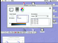
if you ground Sense 0 (Monitor ID 0, S20)to Ground (S21) you should get 640x480.
i haven't used the video mirroring board myself but i would assuming it still relies on the monitor Sense ID to be correctly set

assuming you have those pins configured along with the power rails and have inverted the power on signal you shouldn't need anything else wired up on the harness to get a bootable system (assuming you plug in an external scsi drive)

ive been a bit busy over the Christmas holidays but let me know if there's anything more i can help/clarify about what i did to get my setup working
Hey! Thanks Chopsticks! Pretty good timing, I'm just now messing around with this again. Not sure about my notes from last time because indeed, all I have to do is connect id0 and id1 (s19 and s20) on the analog board 10p connection, and I get video out(!).
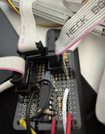
However, I still need to connect the 10p neck-board cable, or else the video out signal (from the mirror-out) is distorted. The neck-board is not connected at all, except for this 10p. I tried to disconnect 1 pin by pin (breadboard cables betweem them), but all of them seem important to get clear video from the mirror-out.

The pin-out from takky for that 10p neck-board cable, has it as brightness and contrast control, r,g,b, -gnd, and rest gnd. I wonder if anyone has done any board to convert that directly to db-15/vga? (I think the performa 630 and 6200 has a video board that this cable connects to).


1737214689266.jpeg
 
@noglin i dont think the brightness and contrast controls would be needed as they are just so you can adjust those from the front panel buttons or in software depending on the machine.. id be interested what happens it you disconnect those two connections though from what you said each connection is needed for clear video so perhaps they need to be tied to ground or VCC. that neck board doesnt appear to have power going to it so i would assume ground ether directly or through a resistor would be worth trying.

secondly as for the RGB signals you could possibly try connecting a 75ohm resistor between each signal and ground and seeing what that does.
in most old equipment RGB signals are usually terminated with a 75ohm resistor and AC decoupling capacitor around 0.1uf to the signal output.
i dont think you would need the decoupling capacitor is this use case though

without a schematic of the neck board and/or some hires pictures of both sides of the PCB im only speculating based on my knowledge RGB from TV's and arcades ect.

regardless let me know how you go

EDIT: also it would be possible to make a board to convert those RGB signals to vga, however you would also need to pull S19-23 from the analogue board (p101) connecter too. as you would need the monitor ID bits to pass through the the mac DB15 video connector (or just hardwire a video res if using a vga connector) and you need the composite sync signal too. i havent looked a that signal under the oscilloscope but its likely you would need sync splitter IC and not all vga monitors will be happy with just composite sync on the H-Sync pin.
probably something like a LM1881 would be the way to go as it would give both H-Sync and V-sync from the Compostic Sync
it would also depend on if those are TTL or analogue signals...
 
Last edited:
I had some time again for this, and got some good progress.
Now it runs on the micro PSU and I get video out - although the display has some ghosting and slight noise. Also I think I made a mistake with the soft boot so that is not yet working, but I can actually take this with me and have a working 5200 now :)


Thanks @Chopsticks - it would be pretty cool to use the RGB signals directly as then you would not need a mirror-cable. But since I have one, I will just make it easy for me for now, although it might be a fun thing to learn how to do that. I added the 75ohm resistors and that helped a lot, thanks!


My notes from what I scribbled down, some work I did without taking notes, so it is not complete. I took voltage readings first with everything connected to original PSU/Analog board and neck board, and then did a bit of detective work to figure out how to connect the things. I also see now when writing this all down here that I've made some mistakes (highlighted below).

Note: the harness is from 5200, which very likely differs from 6200/630 as it has a neck board for the CRT. I've lined it up also with the numbering from Takky on the motherboard - so might still be useful for other harnesses.

"Power Supply" cable (female 10p) goes to CN5 on original PSU
_________
|1 2 3 4 5|
|6 7 8 9 10|
-----___-----
1: -12V (when on). 2: +5V stdby. 3: (this is probably soft boot). 4: +5V. 5: NC. 6,7,8,9: GND.

"Neck board" cable (female 10p)
_________
|1 2 3 4 5|
|6 7 8 9 10|
-----___-----
1,2: NC. 3: Blue. 4: Green. 5: Red. 6,7,8,9: GND, 10: NC.

"Analog board"
_________
|1 2 3 4 5|
|6 7 8 9 10|
-----___-----
1: Monitor Input ID 2. 2: Monitor Input ID 1.

Molex 14P goes from harness to CN14 on original PSU
_________________________
|R1 R2 W03 b04 B05 Y06 Y07| (R: red, W: white, B: brown, Y:yellow, b: black)
|R8 R9 b10 B11 b12 B13 Y14|
-----------------------------------------
R(1,2,8,9): 5V. B and b (4,5,10,11,12): GND. Y(6,7,14): 12V

Takky numbering of the motherboard slot-inTakky comment[V] Original PSU[V] Original PSU and ONOriginally connects to:Now connects to
S1-12V0-121 "Power supply"micro PSU -12V
S2GND006,7,8 "Power Supply"NC
S3ADB
Power Supply
552 "Power Supply"micro PSU +5V Std by
S4GND506,7,8 "Power Supply"NC
S5Power off command0.54.63 "Power Supply"NC
(should be for soft boot?)
S600.7(my note says 6,7,8 but inconsistent with the voltage? either voltage note is wrong or S6 is not connected to 6,7,8)
S7+5V054 "Power Supply"NC
S8
S9Brightness control output1 "Neck board"NC
S10GND? "Neck Board"GND
S11Contrast control output2 "Neck Board"NC
S12-GND? "Neck Board"GND
S13blue3 "Neck Board"75 ohm -> GND
S14GND? "Neck Board"GND
S15green4 "Neck Board"75 ohm -> GND
S16GND? "Neck Board"GND
S17red5 "Neck Board"75 ohm -> GND
S18510 "Neck Board"NC
S19Monitor ID input 21 "Analog Board"S19 and S20 connected
S20Monitor ID input 12 "Analog Board"S19 and S20 connected
...
P1, P2Yellow012Y Molex 1412V micro PSU
P3, P4Grey
(brown 5200)
00brown Molex 14GND micro PSU
P5, P6Grey
(black 5200)
00black Molex 14GND micro PSU
P8Orange
(white 5200)
0.12.9 -> 3.6white Molex 14PCB for soft boot
(not for soft boot?)
P9, P10Red05Red Molex 14micro PSU 5V
P11, P12Red05Red Molex 14micro PSU 5V
 
Last edited:
Glad this popped up again. One of my first manic, worked 'til dawn hacks was installing Q630 board/OEM PSU/FDD into the backside of a Sharp word processor/printer. Nice little portable case with a handle on it. If interested I can take some pics, currently has 6290/Reply DOS Card setup installed, untested. Hacking in a full KBD would be so easy!

edit: I've used empty toolbox cases for a couple of projects, lid would make a good spot for an LCD.
Oh nice. Yeah picture is fun :) My plan is to go for plexiglass cover so that when I bring it, I can put my laptop screen on top of it.
 
OK I fiddled a bit more. I had to connect the monitor id slightly differently so that I would get a multiscan display so I can get all resolutions that the 5200 supports. Even though my DB15->VGA adapter is anyway currently hard-wired for 640x480. Also, I found a mistake on my PCB which helped fix the display issue a bit.

I think that at this point the visual I get is the same that I got when capturing from my real 5200 - unfortunately I cannot compare anymore because the original PSU of my 5200 broke.

The captured video is done via: mirror cable -> DB15 -> VGA -> HDMI -> HDMI capture card -> usb-c on macbook air -> OBS or Quicktime.

Even with lossless on OBS it looks about the same, so I think the issue is signal quality in this chain?

@Chopsticks would you have any suggestion perhaps?
 

Attachments

One odd thing with the video is also that it seems to be offset in x by about 10 pixels (see black area to the left and no rounded corner to the right).

For the signal quality, I think it is because the VGA cable is long, alomst 1M, and the DB15 -> VGA is a hack. I will try make a DB15->VGA that has as short cabling as possible. But not sure what is causing the 10px offset.
 
Last edited:
10px could just be the capture card not getting the porch or some other variable correct. You'll want to see it on a real monitor.
 
@noglin i think mostly the mirror cable probably just ignores sense ID bits and goes on whatever sense id is configured on the internal harness. at least that would make logical sense to me. connecting sense ID 0 to ground was just a easy way to test a widely supported res and refresh rate as at the time i was familiar with what the 5200 actually supported.

as for suggestions to fix the offset, im no obs expert but you could try fiddling with transform settings:
right click on capture under sources then got to Transform>Edit Transform
also check the properties for the capture device in IBS and double check what the Resolution is set too. HDMI doesn't technically support any of those 4:3 resolutions so its really going to up to what you can select here along with what you hdmi capture device does with its incoming signal.
failing all that i personally use a OSSC (Open Source Scan Converter) to 'massage' fussy analogue RGB video signals before sending to a hdmi capture or LCD/TV). you could also try using a RGBtoHDMI it might offer similar help assuming you cant tweak the OBS settings...
 
I can confirm that the Apple External Video Connector is strictly for mirroring: tested in a 6400, if I don’t plug a monitor in the usual video output I don’t get any image. My idea was tu use the Apple External Video Connector with a VGA adapter (that I would have mounted internally) in order to have the choice of DB15 or VGA video output. But alas there’s no sense lines in the Apple External Video Connector, and I didn’t even get an image with only a monitor plugged in this connector. (Maybe the 6400 started in a weird resolution not supported by my monitor)
 
@François its likely that without a monitor connected to the normal db15 video out that mac detects all three sense lines as unconnected/floating so it makes the assumption no display is connected and doesn't enable the video out circuitry on the motherboard.
if you have a mac db15 to VGA adapter plugged in to the normal mac video port even without a monitor the mirroring port will likely work, kinda defeats what you are wanting to do though.
personally i use a adapter or if i cant have the extra length that adds to the back of a mac then i wire up a custom db15 to vga cable myself. i cut a vga cable connect off and replace with a standard db15 connect and hardwire the sense pins usually as either sense 0 to ground or i use some diodes and set it up for SuperVGA
 
Back
Top