• Hello MLAers! We've re-enabled auto-approval for accounts. If you are still waiting on account approval, please check this thread for more information.

PM 5400 / 5500 Damage? Compatibility?

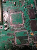
Well, sadly, the reflow of the video chip was unsuccessful. It looks good, however now there's no happy chime. Probably my sub-par skills. Have gone over the board with a fine-toothed-comb, however it's going into the "for parts or repair" pile for now. Think it's time to start looking into replacements. So it seems like R49/R44 is a good way of checking whether a board needs 3.3v mod?

If there's interest, can use this thread to instead begin to try and resurrect the world's dirtiest LC 575 board, instead of creating a new one?
 
Carry on as you wish, I think. Do you have desoldering braid? You might have a solder bridge between pins that could be sorted as such.
 
Found what the issue is - on two sides of the chip, the small traces under what looks to be (from looking at your diagram) HSYNC, VDDC, EVIDEO & BLANK, and also a few of the PIXEL# pins were destroyed by the corrosion - they aren't there at all. Perhaps with a supremely steady hand it would be possible to bodge these further down the traces? -edit- looks like well beyond my ability, sadly.
 
Last edited:
EVIDEO I don't remember, BLANK and the pixel bus can probably be ignored, VDDC might be redundant, but missing HSYNC will absolutely leave you no working video output. But yeah, should be bodgeable alright. Care to post a pic? Save it for later maybe, after you have more practice.
 
Sure - see below. Camera isn't great and seems to add a fair bit of "mushing" between the various elements, so it's hard to see on the right side... the lifted pads (& 1 slightly bent pin where I used a needle to check below) on PIXEL# are very visible on the bottom row. Sadly they came straight off during the reflow - must've been caked together:

4.jpg


5.jpg
 
Sure - see below. Camera isn't great and seems to add a fair bit of "mushing" between the various elements, so it's hard to see on the right side... the lifted pads (& 1 slightly bent pin where I used a needle to check below) on PIXEL# are very visible on the bottom row. Sadly they came straight off during the reflow - must've been caked together:

View attachment 61814


View attachment 61815
It's a bit hard to see in the picture, but do you have some flux? (The soldering aid, not the old name for TB). Flux helps tidy up solder and sort of... Pull it in line.

When someone tells you "a bad workman blames their tools", they've never tried soldering with and without flux.
 
And remember, this is fairly common: this (abandoned) 6360 lost three and a half on the CPU (on the half, pin eaten, pad vanished, trace broken before next component), and three on the video, plus some broken traces under the CPU, plus battery gunk inside the CPU. So don't be too harsh on yourself: sometimes these things blow themselves up bad.
 

Attachments

  • 16943049325734251805166799592052.jpg
    16943049325734251805166799592052.jpg
    1.6 MB · Views: 9
@Phipli sadly, this is the result of using a fair bit of flux, too tricky for me.

@GRudolf94 Thanks, guess that does make me feel a little better. It was such an anticlimax, to have the "happy bong", and then for it to fall apart in front of me. It'll be stowed for a rainy day, and a replacement will turn up without too much hunting. Next is the aforementioned LC 575, which should hopefully be less traumatic. Thanks for your and everyone's help!
 
which looks dusty but nothing standing out as leaking.
That doesn’t mean a whole lot. These tend to not have obvious leakage. Sometimes you can only see it once the capacitor is removed. Also - a capacitor can go out of spec / be bad without obvious leakage.

Just something to bear in mind for future reference.
 
Guessing there was a certain point in time where they used a different quality capacitor?


Haven't seen any of these machines in the flesh yet! Is the longevity one of the reasons they're sought-after?
They were mostly premium machines and some of the fastest 68k macs. One of the benefits of premium is that they were built with tantalum capacitors which don't contain a liquid to leak.

Some IIfxes were also built with tantalums, but not all.
 
So, have stumbled across a cheap 6300/120 board, that doesn't appear to have been batt. bombed yet.

1.jpg

Is there a guide anywhere detailing the 3.3v mod? As in which parts to buy, what to solder to what? Assuming this needs it.
 
While these are much less likely to be batt bombed due to the use of alkaline 4.5 batteries, I don’t think you need any 3.3 on the 6300 - it does not jave a PCI slot
 
That's good news. Have seen pics of people just soldering + and - to a CR2032 as a replacement - is this legit?

With regards to the 3.3v, so, with a board that doesn't have the PCI slot, it can go into the 5500 because those boards didn't require 3.3v? In another thread it was all quite confusing to me as they were talking about pre-PCI boards having a slightly different pinout.
 
Back
Top