-
 Hello Guest! We're hosting a challenge to welcome vintage Intel macs to the MLA during the month of July! See this thread for more information.
 -
We've made some quality of life improvements to the Trading Post. More info here.
You are using an out of date browser. It may not display this or other websites correctly.
You should upgrade or use an alternative browser.
You should upgrade or use an alternative browser.
Macintosh Plus analog board issue
- Thread starter ijnfuso
- Start date

Welp, the other day I got a new analog board. Recapped the three RIFAs, the seller said it was taken from a working mac, and guess what? It still has the same issue! I really have no idea.... could it be a CRT issue? Maybe the CRT has weird current draws or has issues, I don't know. Really stuck!
View attachment 79614525281__A319A84C-796A-4C5C-8794-1B6A55DB8828.mov
View attachment 79614525281__A319A84C-796A-4C5C-8794-1B6A55DB8828.mov

I already tried lowering the voltage and it did not change anything. I also reseated the rom, the ram, tried putting in a battery, but I got no luck whatsoever.try lowering down the voltage
Welp, the other day I got a new analog board. Recapped the three RIFAs, the seller said it was taken from a working mac, and guess what? It still has the same issue! I really have no idea.... could it be a CRT issue? Maybe the CRT has weird current draws or has issues, I don't know. Really stuck!
View attachment 96983
It’s pretty much a given that since you’ve swapped the analog board and the symptoms haven't changed at all, the trouble is likely living on the logic board. You can definitely stop worrying about those RIFAs for now. They’re just there to filter RF noise on the AC lines and won't actually stop the machine from booting or cause logic issues.
The great news is that you're getting a boot chime! That’s a huge win because it means your CPU is alive, running code, and successfully talking to the ROMs. Since we can probably rule out the analog board, here’s where I’d focus your energy on the logic board to stop that chime loop.
One fairly common cause of a boot chime loop is the reset circuitry.
Since you're testing without the case, we know the plastic buttons (the Reset and Programmer switches) aren't physically stuck, but the circuit itself could still be latching low. On the Mac Plus, the Reset and Interrupt lines are 'open collector,' meaning multiple components can pull them to ground to trigger a restart.
Even without the external switch, the physical push-buttons on the board can internally short or get gunked up with debris, making them trigger with the slightest vibration.
It’s worth checking the continuity on those switches or using a logic probe to see if the HALT or RESET pins on the 68000 are pulsing low when they shouldn't be. If a buffer chip in that path has failed, it might be holding the CPU in a permanent reboot cycle.
Last edited:
Another common cause of boot chime loops in this machine is the RAM SIMM configuration or the RAM itself (assuming, of course, that your DC voltages are within acceptable tolerances.)
Also, have you reflowed the solder joints on the J1 connector on your logic board and analog board? You would be surprised how often cracked joints on J1 produce all sorts of issues in this machine. If you haven't done so yet, could you post a close-up picture of those joints?
Don't give up! You are almost there. it seems you have no more issues with the circuitry of your AB, and that is a big thing!
I just checked the continuity, and both of the switches work as intended, nothing when the switch is not pressed.It’s worth checking the continuity on those switches or using a logic probe to see if the HALT or RESET pins on the 68000 are pulsing low when they shouldn't be. If a buffer chip in that path has failed, it might be holding the CPU in a permanent reboot cycle.
Well last time this thing worked the RAM wasn't a problem... I also tried reseating it and cleaning the connectors both on MB and RAM, and nothing changed.Another common cause of boot chime loops in this machine is the RAM SIMM configuration or the RAM itself
Haven't reflowed it... I guess the joints look kind of cold- soldering is not my strong point, all my experience comes from soldering some floppy drives and this macintosh...J1 produce all sorts of issues in this machine. If you haven't done so yet, could you post a close-up picture of those joints?

(assuming, of course, that your DC voltages are within acceptable tolerances.)
I monitored the 12v and 5v voltages using the floppy port method and, I'm honestly quite afraid of the resultsCan you try monitoring voltages ? You should know what you are dealing with.
Even when the knob on the AB is set to minimum voltage, the 12V ranges from 11 with a couple of spikes to 14 and 5V was from 4 to 6, almost 7 volts. Now, I'm unsure about this since It's kind of hard getting decent measurements with the mac constantly boot looping, so, the results might be off
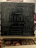
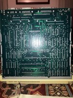
I attach the images I took of J1 (even on the logic b.) ((i never know)), and of the entire logic board
If you need me to take pictures of certain joints or components ask away, anything is welcome
Attachments
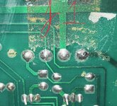
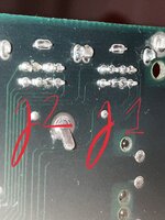

The solder joints on your J1 connector (4 pins) on the AB look quite bad; some cracks are even visible. You also need to check the solder joints highlighted in the attached picture.
You're right, those at j1 look like cold solder joints.
The voltage spikes you are seeing are likely due to the machine's restart loop.
You need to reflow all hairline cracks and bad solder joints on the analog board connector sockets. To do this properly, I recommend removing as much of the old solder as possible, then using a generous amount of flux and new solder. Since these joints are large, your soldering iron needs to be powerful enough to generate the heat required for a solid connection.
Do not try to move or pull the connector pins, or you could end up lifting the pads. Perform the work with the connectors plugged in; this ensures the pins on the socket will not move or become misaligned.
IMHO the safest method to remove solder from those large joints is the 'Wick and Flux' method.
What kind of probe are you using to measure the voltages?.
I guess you already tried to boot the machine without the floppy drive ribbon cable connected right?
To get an accurate reading, clip the ground lead to the chassis (ensuring the analog and logic boards are properly grounded to the chassis with screws) and the positive probe to the correct floppy port pin.
Last edited:
You need to reflow all hairline cracks and bad solder joints on the analog board connector sockets.
Thanks for the tip... I'll do that tomorrow and update the thread after I reflow every bad joint (it's 1:30 am and I'm very tired)
Here I am, a bit late (I got sick) but I bring news.
Good news is that the computer didn't explode after the resoldering!
Bad news is that the issue is still the same, still this damn chime loop over and over again. Might be worth to mention that (this happened even before) when for the first time it chimes (after giving it power), it takes 2-3 seconds for it to start looping, after that it just loops endlessly with a very fast restart rate
I'm honestly surprised this issue is still going...
(sorry for the broken english, not my first language plus I'm still not completely well, lol)
I have reflowed every cold/cracked joint on the board and every connector joint, and double checked afterwards... to be honest, there weren't many but I still resoldered the connectors for good measure.You need to reflow all hairline cracks and bad solder joints on the analog board connector sockets.
Readings without the floppy attached still read as the ones I did before so, nothing much changed.I guess you already tried to boot the machine without the floppy drive ribbon cable connected right?
Good news is that the computer didn't explode after the resoldering!
Bad news is that the issue is still the same, still this damn chime loop over and over again. Might be worth to mention that (this happened even before) when for the first time it chimes (after giving it power), it takes 2-3 seconds for it to start looping, after that it just loops endlessly with a very fast restart rate
I'm honestly surprised this issue is still going...
(sorry for the broken english, not my first language plus I'm still not completely well, lol)
Optoisolator ?
To be honest, the CRT swap was not relevant, unless they are broken, they cannot give this kind of problem.
The issue with voltages going all other the place are usually related to the Optoisolator, there is no way to troubleshoot this item, but the part is cheap ans socketed.
To be honest, the CRT swap was not relevant, unless they are broken, they cannot give this kind of problem.
The issue with voltages going all other the place are usually related to the Optoisolator, there is no way to troubleshoot this item, but the part is cheap ans socketed.
On the old analog board I changed it, and this other analog board had already a changed one. So I either bought a bad optoisolator, an analog board with a new bad optoisolator or the logic board is laughing at me..The issue with voltages going all other the place are usually related to the Optoisolator, there is no way to troubleshoot this item, but the part is cheap ans socketed.
Edit; even with it changed the issue is still the exact same.
Hello! Greetings from Porto Alegre, Brazil. Just fired up my old Mac Plus stored for years and it's doing the same chime loops and the screen blinks sometimes showing the background pattern. After a while it becames silent and the screen blacks. Will follow this topic and try to find the culprit as well, reporting here my findings. I've attached a video showing the issue - I'm counting in portuguese the chimes "um" (one) "dois" (two)....On the old analog board I changed it, and this other analog board had already a changed one. So I either bought a bad optoisolator, an analog board with a new bad optoisolator or the logic board is laughing at me..
Edit; even with it changed the issue is still the exact same.
Attachments
Did the Mac Plus ever get sent in for the recall? If not, it's likely the cold solder on the CRT harness; just needs any cracked solder joints reflowed IIRC. Of course, remove the battery if it's still in there, tooHello! Greetings from Porto Alegre, Brazil. Just fired up my old Mac Plus stored for years and it's doing the same chime loops and the screen blinks sometimes showing the background pattern. After a while it becames silent and the screen blacks. Will follow this topic and try to find the culprit as well, reporting here my findings. I've attached a video showing the issue - I'm counting in portuguese the chimes "um" (one) "dois" (two)....
")
Thanks! This Mac Plus, I've bought it at 2014 from an eBay seller. It shipped from USA. Arrived working. Then it went to my storage. I'll check for cold solder points.Did the Mac Plus ever get sent in for the recall? If not, it's likely the cold solder on the CRT harness; just needs any cracked solder joints reflowed IIRC. Of course, remove the battery if it's still in there, too
I’m very familiar with this board. Unfortunately it’s too far away—otherwise you could just send it to me for repair.
Because remote debugging is much more difficult than observing it in person with an oscilloscope.
Focus on checking the bridge rectifier and the main switching BJT of the switching power supply. A short circuit on the +12V or +5V load could also cause this issue.
Because remote debugging is much more difficult than observing it in person with an oscilloscope.
Focus on checking the bridge rectifier and the main switching BJT of the switching power supply. A short circuit on the +12V or +5V load could also cause this issue.
Similar threads
- Replies
- 4
- Views
- 442
- Replies
- 5
- Views
- 451