-
 Hello Guest! We're hosting a challenge to welcome vintage Intel macs to the MLA during the month of July! See this thread for more information.
 -
We've made some quality of life improvements to the Trading Post. More info here.
You are using an out of date browser. It may not display this or other websites correctly.
You should upgrade or use an alternative browser.
You should upgrade or use an alternative browser.
Macintosh 128k 630-0101 board with “jailbars”
- Thread starter Joopmac
- Start date

Look for a pair of shift registers (74LS166 at UF13 and UF14 according to the schematic that I found). Eight pins on each chip are supposed to connect to different RAM data output lines. One of those connections is probably bad. It's clearly not the RAM chips themselves, as the system boots to this point. And it's possible that it's one of the shift registers themselves, but that feels less likely than it being a blown trace.
Audio pulls from the RAM using a shared data path, though it's the pair of 74LS161 chips at UE15 and UF15. I'd have to do a bit of digging to understand quite how it gets from eight bits of data to an analog audio signal, though my current intuition is that it's using counters to generate a PWM signal and then an op-amp to integrate that.
At any rate, this lends support to the theory of it being a bad trace, and tells us that it's one of the traces feeding UF13, after it feeds UE13 (which is a 74LS244 and drives the values that the CPU sees for D8-D15, since the system boots we know that this chip is connected and working), and feeds either UE15 or UF15. Check continuity between pins 3, 4, 5, and 6 of UE15 and UF15 and pins 2, 4, 6, 8, 11, 13, 15, and 17 of UE13. Also between pins 2, 3, 4, 5, 10, 11, 12, 14 of UF13 and UE13.
I'm thinking that a break on pin 2 or 11 of UE13 is most likely for both audio and video. And, looking at your screenshot above, pin 2.


")
Ten-pin thing, half its legs cut off, attached to pins 34-38 and C30? Looks like extra pull-ups on A9-A12, or low-maybe pull-downs (they'd conflict with RP1, which is all the way across the board if they were pull-downs). If so, I'm not sure why it's there (though it's probably to do with having a valid state at the NMOS VIA register selects before the CPU is driving the bus and RP1 not being close/strong enough to do the job), but it's almost certainly original.
Cool insight, thanks.
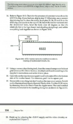
I found this nice piece of information in Macintosh Repair & Upgrade secrets
And after googling a lot 128k logic boards and their images, i found that some of them have, and some of them don't - also early ones like week 6 can have it all the way up until week 43, only the shape of the resistorpack has changed throughout the year. And it is recommended for all 128k's, Larry Pina says even required with 512K RAM IC upgrades.
but certainly not all 128k's have this, this the first resistorpack on that strange location on a multitude of m0100X's i have, i first thought it had to do with a 512K upgrade board
Not sure if it's a official Apple Service Bulletin or something from 1984=)
Attachments
How odd. The fan-out on those lines is only four, maybe five if the RAM upgrade also taps them (both ROM chips, the VIA, and split over a couple of address multiplexers, probably using some as row addresses and some as column addresses). Maybe it's something to do with trace length, with the VIA being basically the opposite side of the board from the address logic, combined with NMOS' atrocious upwards drive strength? At any rate, it seems clear that you should have it installed.

 )
)

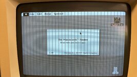
You showed an image with the system running and showing the Finder's about box. It is vanishingly unlikely to be the CPU. Also note that this means that the system had to have passed its basic RAM tests, so it's not anything in the direct path between CPU and RAM in either direction. The display image is recognizable, so it's not the video address generation logic or anything after the display shift registers. What's left to check? I still say a broken trace between one of the shift registers and RAM is a likely culprit.Is it possible that the CPU is defective?
A CPU problem such that it passes the startup RAM test and runs the Finder yet has a consistent single-bit error when writing to video memory? This feels unlikely, but I suppose it could be possible.
How about this? Drag a finder window slightly to the side (just a few pixels, certainly not as many as sixteen pixels), and see if also drags a copy of the jailbars with it? If the jailbars get copied then we're looking at something between the CPU and RAM (since the CPU is reading the jailbars as it does a bitblt). If they don't (the CPU is working with good data), then it's the video output path.
How about this? Drag a finder window slightly to the side (just a few pixels, certainly not as many as sixteen pixels), and see if also drags a copy of the jailbars with it? If the jailbars get copied then we're looking at something between the CPU and RAM (since the CPU is reading the jailbars as it does a bitblt). If they don't (the CPU is working with good data), then it's the video output path.
Similar threads
- Replies
- 0
- Views
- 93