Hi folks,
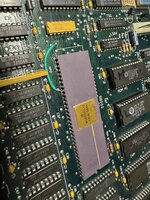
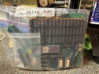
I recently managed to score a Mac 512K "outfitted" with a Levco MonsterMac/OverDrive upgrade combination that gives it 2 MB of RAM and an internal SCSI hard drive for a pretty good price! I am quite excited - I've been looking for one of these upgrade packages for a while to compare to my HyperDrive 512K - but there is a fairly large asterisk to the cheap price that I need to take care of first. I put "outfitted" in quotations because the upgrade itself was sent to me outside of the Mac, and from talking to the seller and looking at the Mac itself it's transparently obvious the upgrade stopped working at some point, and in an attempt to just get the machine to function again, someone slapped in a spare 68K (a 10 MHz part!) and bagged up all of the leftover parts.
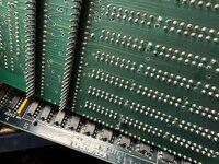
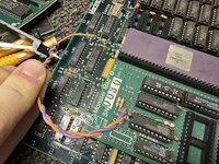
Although not difficult at all to reinstall the upgrade physically, I am running into a bit of a roadblock regarding a few extra connections beside the CPU piggyback itself I cannot seem to concretely pinpoint on the logic board. There are a pair of red and purple wires, with the purple wire cut and wrapped around the red wire, with a female pin header connection on the end. In pictures of other Monster Mac upgrades I've seen online, the cut wire seems to be normal, and the red wire connects to a via (?) below IC BMU1 on the logic board, but no pictures I can find zoom in enough to show precisely where, and there's not really any evidence this logic board has been modified to accommodate the wire. There is also a single pin underneath the Monster Mac board itself, roughly centered around a separate patch of vias on the logic board, that I have no idea what to do with at all. As found, it was folded over in a somewhat violent manner.
I suppose my question is, if anyone out there has a functional Monster Mac-upgraded machine, could you please take some good pictures of where these extra connections go? It would be extraordinarily appreciated!! I have a DIP64 socket and a few other miscellaneous parts in the mail, so it'll be a little while before I can start final assembly, but in the meantime I'm trying to do as much research as possible and this has left me a bit stumped. I do not believe anyone has digitized the installation instructions that would presumably cover this. Thanks!
I recently managed to score a Mac 512K "outfitted" with a Levco MonsterMac/OverDrive upgrade combination that gives it 2 MB of RAM and an internal SCSI hard drive for a pretty good price! I am quite excited - I've been looking for one of these upgrade packages for a while to compare to my HyperDrive 512K - but there is a fairly large asterisk to the cheap price that I need to take care of first. I put "outfitted" in quotations because the upgrade itself was sent to me outside of the Mac, and from talking to the seller and looking at the Mac itself it's transparently obvious the upgrade stopped working at some point, and in an attempt to just get the machine to function again, someone slapped in a spare 68K (a 10 MHz part!) and bagged up all of the leftover parts.
Although not difficult at all to reinstall the upgrade physically, I am running into a bit of a roadblock regarding a few extra connections beside the CPU piggyback itself I cannot seem to concretely pinpoint on the logic board. There are a pair of red and purple wires, with the purple wire cut and wrapped around the red wire, with a female pin header connection on the end. In pictures of other Monster Mac upgrades I've seen online, the cut wire seems to be normal, and the red wire connects to a via (?) below IC BMU1 on the logic board, but no pictures I can find zoom in enough to show precisely where, and there's not really any evidence this logic board has been modified to accommodate the wire. There is also a single pin underneath the Monster Mac board itself, roughly centered around a separate patch of vias on the logic board, that I have no idea what to do with at all. As found, it was folded over in a somewhat violent manner.
I suppose my question is, if anyone out there has a functional Monster Mac-upgraded machine, could you please take some good pictures of where these extra connections go? It would be extraordinarily appreciated!! I have a DIP64 socket and a few other miscellaneous parts in the mail, so it'll be a little while before I can start final assembly, but in the meantime I'm trying to do as much research as possible and this has left me a bit stumped. I do not believe anyone has digitized the installation instructions that would presumably cover this. Thanks!