

I’m also awake at a silly hour. Seems Mac fanatics are always up at weird hours to help each other out.
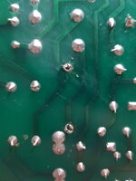
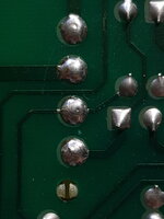
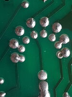
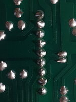
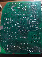
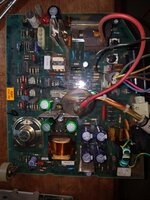
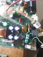
I’d start with the basics - when you say you power it on and nothing, do you mean no display and no chime? Make sure the brightness is turned up. Your board likely needs multiple solder joints reflowing, in particular the yoke connector and logic board power ones. High temperatures in the compacts without a fan cause the analog board to overheat and hence the solder joints to crack.
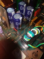
Analog boards carry high voltages that can kill you - please make sure you discharge the CRT before working on it and don’t poke around there with it powered on unless you really know what you are doing.
I’d start with the basics - when you say you power it on and nothing, do you mean no display and no chime? Make sure the brightness is turned up. Your board likely needs multiple solder joints reflowing, in particular the yoke connector and logic board power ones. High temperatures in the compacts without a fan cause the analog board to overheat and hence the solder joints to crack.
Analog boards carry high voltages that can kill you - please make sure you discharge the CRT before working on it and don’t poke around there with it powered on unless you really know what you are doing.


![20221118_204356[1].jpg](/bb/data/attachments/49/49163-67b37411d24182c0521c170f3032ae32.jpg?hash=Z7N0EdJBgs)
